Substrate processing apparatus

a processing apparatus and substrate technology, applied in the direction of coatings, metallic material coating processes, chemical vapor deposition coatings, etc., can solve the problems of degrading and achieve the effect of improving the quality of substrate processing

Active Publication Date: 2017-09-07
KOKUSA ELECTRIC CO LTD
View PDF3 Cites 185 Cited by
  • Summary
  • Abstract
  • Description
  • Claims
  • Application Information

AI Technical Summary

Benefits of technology

[0007]Described herein is a technique that...

Problems solved by technology

This can degrade the qu...

Method used


Image

  • Substrate processing apparatus
  • Substrate processing apparatus
  • Substrate processing apparatus

Examples


first embodiment

[0026]The first embodiment will be described with reference to the drawings.

[0027]The substrate processing system according to the first embodiment will be described below.

[0028](1) The Configuration of the Substrate Processing System

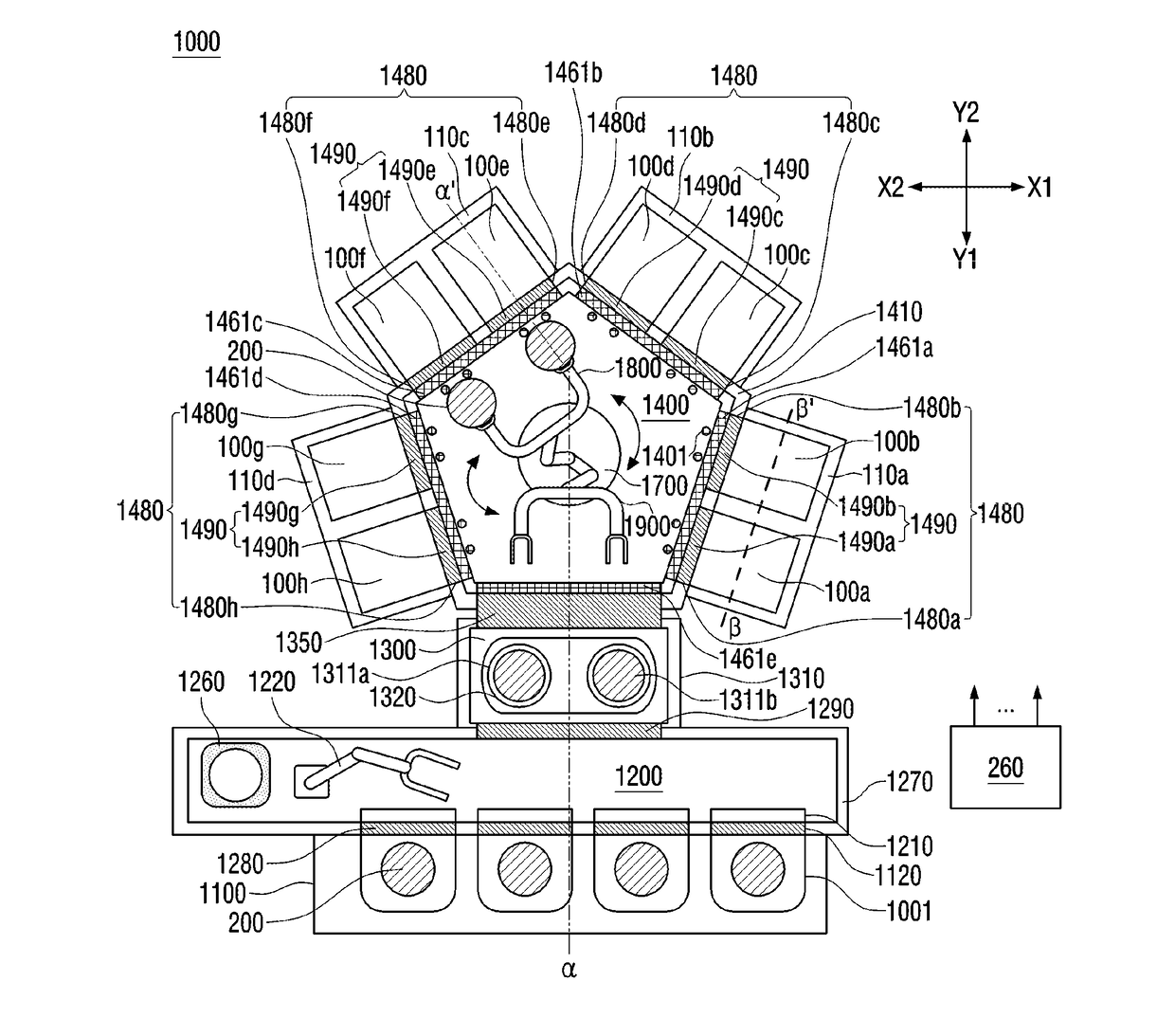
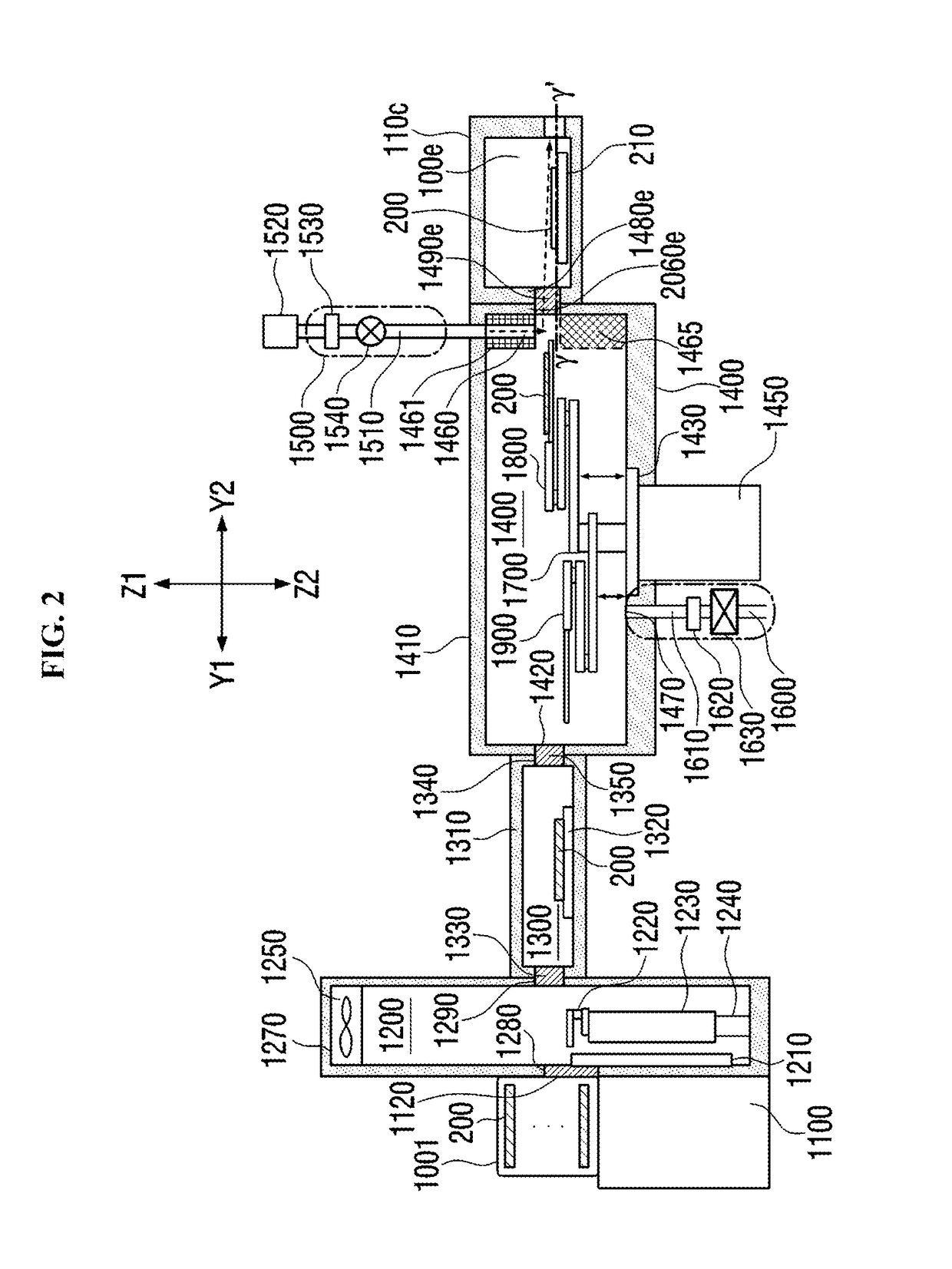
[0029]The configuration of the substrate processing system according to the first embodiment will be described with reference to FIG. 1 through FIG. 11. FIG. 1 illustrates the horizontal cross-section of the substrate processing system according to the first embodiment. FIG. 2 illustrates a vertical cross-section of the substrate processing system according to the first embodiment shown in FIG. 1 taken along the line α-α′. FIG. 3 illustrates the cross-section taken along the γ-γ′ line in FIG. 2 seen from the Z1 direction. For the purpose of description, components such as a vacuum transfer robot 1700 are not shown in FIG. 3. FIG. 6 illustrates the relationship between the positions of the first gas supply unit 1500 and the wafer 200 of the substrate pro...


PUM

PropertyMeasurementUnit
Flow rateaaaaaaaaaa
Heightaaaaaaaaaa
Distanceaaaaaaaaaa

Abstract

Described herein is a technique that can improve a quality of substrate processing. A substrate processing apparatus may include: a plurality of processing chambers; a vacuum transfer chamber; a plurality of transfer chambers; a plurality of gate valves; a plurality of first gas supply units configured to supply an inert gas to a substrate; a transfer robot; and a control unit configured to control the plurality of first gas supply units and the transfer robot to: supply the inert gas to the substrate at a first flow rate when a distance between a gas supply port and the substrate passing through the plurality of gate valves is a first distance; and supply the inert gas to the substrate at a second flow rate greater than the first flow rate when the distance between the gas supply port and the substrate is a second distance greater than the first distance when the substrate passes through the plurality of gate valves.

Description

CROSS-REFERENCE TO RELATED PATENT APPLICATION[0001]This non-provisional U.S. patent application claims priority under 35 U.S.C. §119 of Japanese Patent Application No. 2016-040011, filed on Mar. 2, 2016, the entire contents of which are hereby incorporated by reference.BACKGROUND[0002]1. Field[0003]The present disclosure relates to a substrate processing apparatus.[0004]2. Description of the Related Art[0005]The process of forming a film on a substrate by supplying a process gas and a reactive gas to the substrate is performed as one of the manufacturing processes of the semiconductor device.[0006]Particles can be attached to the substrate during transport of the substrate. This can degrade the quality of substrate processing.SUMMARY[0007]Described herein is a technique that can improve the quality of substrate processing.[0008]According to one aspect of the technique described herein, a substrate processing apparatus may include: a plurality of processing chambers where a substrate...

Claims


Application Information

Patent Timeline
IPC IPC(8): C23C16/455H01L21/02C23C16/34C23C16/44C23C16/52
CPCC23C16/45544C23C16/4408C23C16/4412C23C16/45527H01L21/0228C23C16/52C23C16/345H01L21/0217C23C16/45565H01L21/67253H01L21/67703C23C16/54H01L21/67196H01L21/67742H01L21/67748H01L21/67754H01L21/67766H01L21/67772H01L21/67167H01L21/67389H01L21/67376H01L21/67201
Inventor YAHATA, TAKASHI
Owner KOKUSA ELECTRIC CO LTD
Why Eureka
Try Eureka