

Motor vehicle lighting device comprising light modules cooled by means of a generator of an air flow
- Summary
- Abstract
- Description
- Claims
- Application Information
AI Technical Summary
Benefits of technology
Problems solved by technology
Method used
Image

Examples
Embodiment Construction
[0046]The elements that are identical, by structure or by function, appearing on various figures retain, unless otherwise specified, the same references.
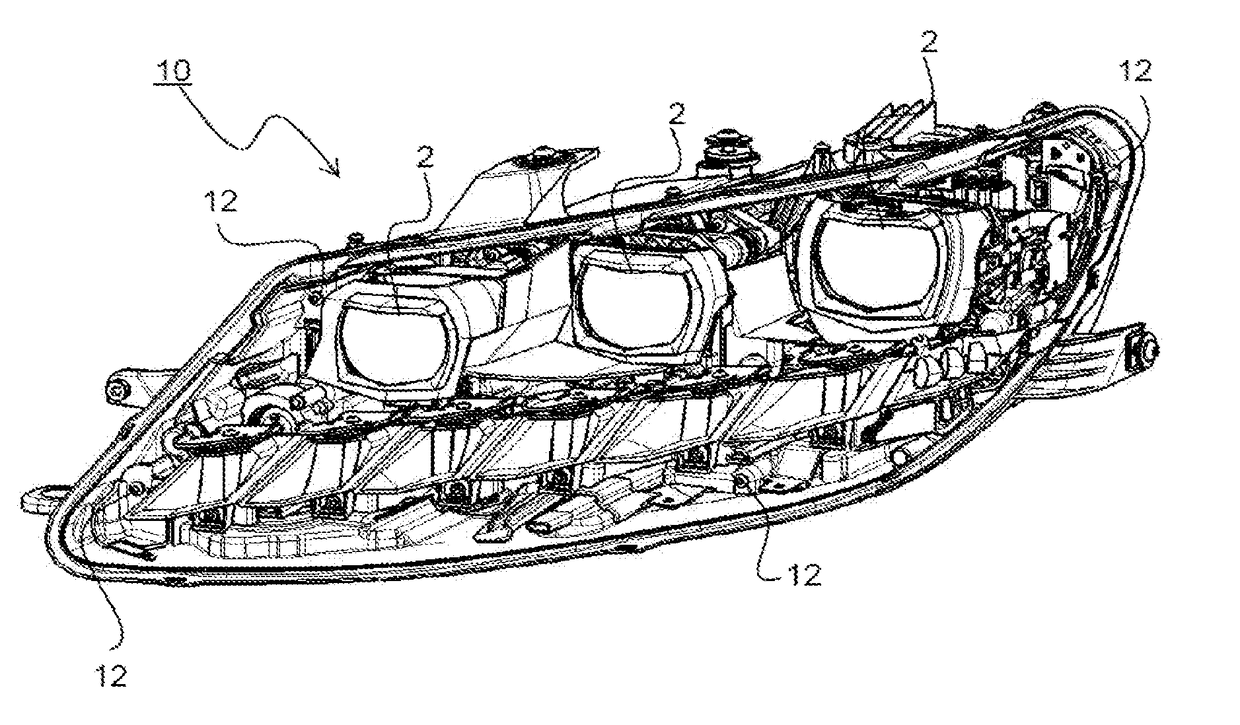
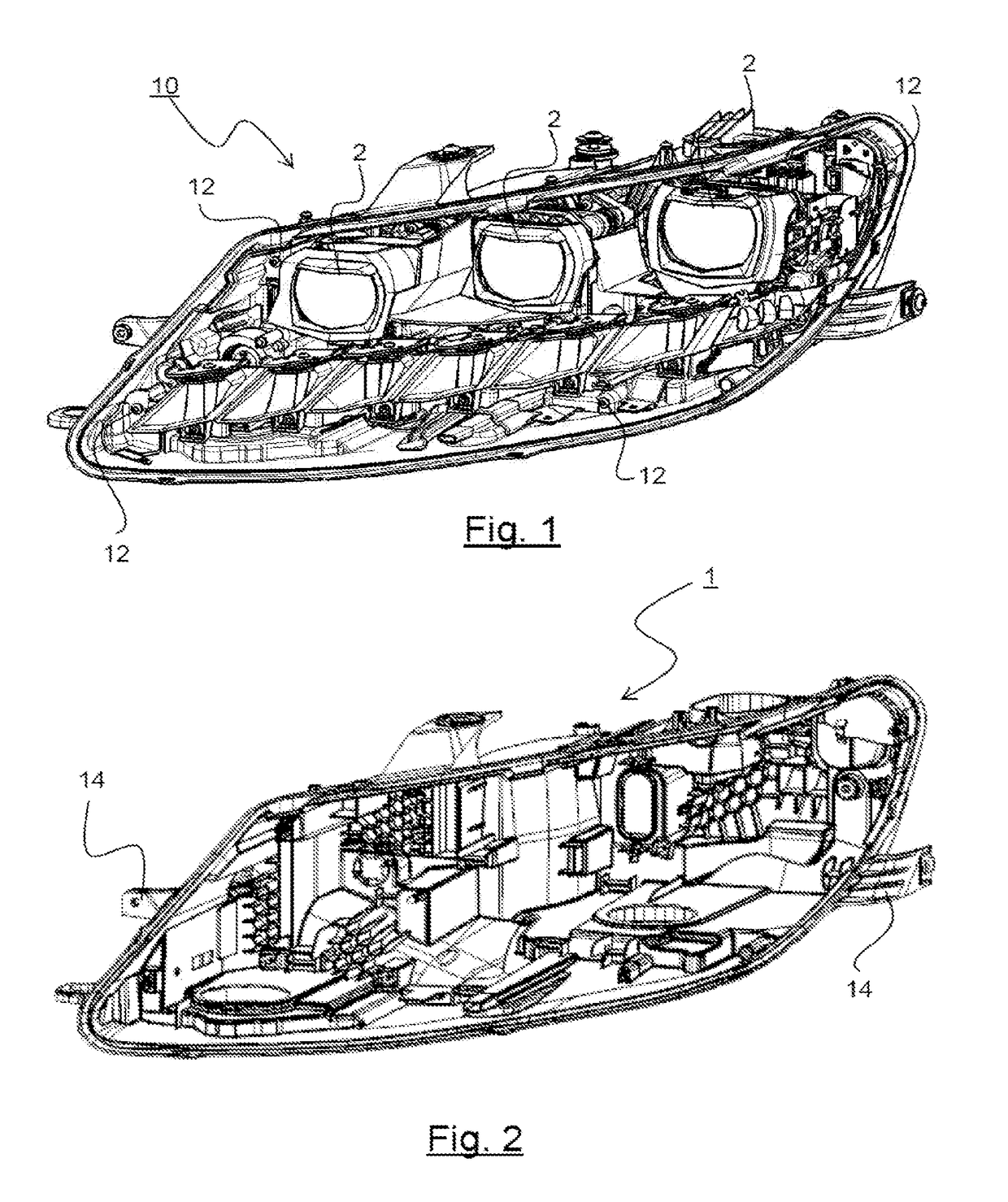
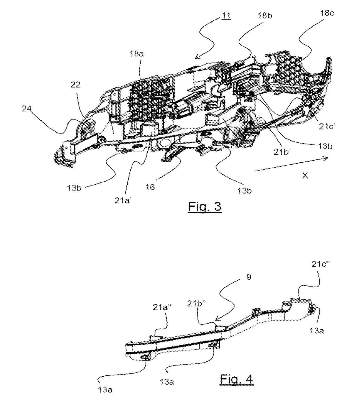
[0047]The motor vehicle lighting device 10 according to the invention is described with reference to FIGS. 1-11.
[0048]Motor vehicle means any type of motorized vehicle.
[0049]In a non-limiting example taken in the remainder of the description, the lighting device 10 is a headlight.
[0050]The lighting device 10 comprises:[0051]structural elements 1, 11 including a housing 1;[0052]at least one light module 2 accommodated inside said housing 1;[0053]a generator of an air flow 5; and[0054]a single air duct 7 suitable for cooperating with said generator of the air flow 5.
[0055]In a non-limiting embodiment, the lighting device 10 comprises a plurality of light modules 2. In the non-limiting example illustrated, the lighting device 10 comprises three light modules 2.
[0056]A light module 2 comprises:[0057]at least one light source (not illust...
PUM
 Abstract
Description
Claims
Application Information