Medium-voltage cable joint

Inactive Publication Date: 2017-09-07
REPL INT
View PDF11 Cites 2 Cited by
  • Summary
  • Abstract
  • Description
  • Claims
  • Application Information

AI Technical Summary

Benefits of technology

[0011]In these various aspects of the invention, a partial discharge detector is arranged or arrangeable around the butt joint between the cables and can be used to test and/or to monitor the join. The conductive sheath of the detector acts as an antenna to detect transient voltages induced by the current spikes in the conductor created by the partial discharge events. The sheath can be in the form of a cylinder with an axial slit therein, to aid in fitting the detector around the join and in sizing the detector to the exact dimensions of the join as made up in the field. A small gap between the opposing edges

Problems solved by technology

A serious flaw in the joint will result in failure immediately or within hours or days, but a more minor flaw may take a considerable time to manifest itself.
During this time, partial discharge is tak

Method used


Image

  • Medium-voltage cable joint
  • Medium-voltage cable joint
  • Medium-voltage cable joint

Examples


Example

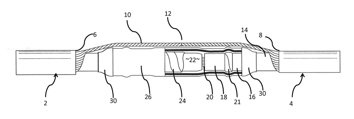
[0020]FIG. 1 shows a conventional joint between two cables 2, 4, each of which has a robust yet to some extent flexible, weather- and waterproof outer covering which is shown cut back to the points 6, 8 for the purposes of making the join. The cables are essentially identical, each comprises several layers and the join is substantially symmetrical along the axis of the cables (from left to right in the drawing); for clarity, some elements which are common to both cables or to both ends of the join are shown in the drawings and described below only in respect of one of the cables. Shown extending longitudinally between the cables 2, 4 and radially between the outer covering and an inner insulator 14, and rolled back so that the join is visible is a mesh of screening wires 10 which run the length of the cables 2, 4 and are joined (shown schematically at 12 so as to provide a continuous earth.

[0021]Underneath the outer sheath, each cable has a layer 16 which is a semi-conductive screen...


PUM


Abstract

A kit for joining opposing ends of two medium-voltage (between about 3.3 kV and about 52 kV) electrical power distribution cables, comprising an electrically-conductive connector for connecting the conductors of the cables, an electrically-insulating surround material for enveloping the connector, a partial discharge detector, comprising a generally cylindrical, electrically-conductive sheath around the insulating surround, from which an electrically-conductive element extends in an axial direction along the length of at least one of the cables, an outer protective tube for surrounding the remainder of the kit, wherein the conductive element is sufficiently long to project out of the protective tube. A partial discharge detector and a medium voltage cable run are also described.

Description

FIELD OF THE INVENTION[0001]The present invention relates to joints in electrically insulated medium-voltage electrical power distribution cables.BACKGROUND ART[0002]The electrical power industry uses four main voltage levels: Low Voltage is up to about 1 kV; Medium Voltage is between about 3.3 kV and about 52 kV; High-voltage is between about 72 kV and about 150 kV, and Extra-High Voltage is above about 220 kV. Medium voltage insulated, cables are commonly used for underground power distribution networks. They differ from extra-high or high-voltage air-insulated cables used for overhead transmission lines in that the conductor is surrounded by a number of electrically insulative, conductive and / or protective layers, usually including a dielectric insulating layer of (typically) a cross-linked polyethylene (XLPE), and a conductive earth sheath. These surrounding layers enable the cable to be buried safely, even in urban areas.[0003]One known difficulty with such cables is in joining...

Claims


Application Information

Patent Timeline
IPC IPC(8): H02G1/14H01B9/00H02G15/18
CPCH02G1/14H01B9/006H02G15/1806G01R31/14H02G15/18H02G15/188G01R31/083
Inventor PATEL, RUTTON HOMIPERETTO, LORENZO
Owner REPL INT
Why Eureka
Try Eureka