
Generator for a power plant

a technology for generators and power plants, applied in the direction of machines/engines, liquid fuel engines, magnetic circuit shapes/forms/construction, etc., can solve the problems of reducing the efficiency of the generator, heating the end winding, and adding resistance losses, so as to improve the cooling effect and the effect of higher efficiency

Inactive Publication Date: 2017-09-07
SIEMENS AG
View PDF44 Cites 9 Cited by
  • Summary
  • Abstract
  • Description
  • Claims
  • Application Information

AI Technical Summary

Benefits of technology

The invention is a new generator that has improved cooling and higher efficiency. The fan creates a cooling air stream that helps remove heat from the bracket connections and stator end winding. This results in generators that are more powerful and efficient, even at the same size.

Problems solved by technology

The use of brackets gives rise to additional resistance losses, which lead to heating of the end winding.
The increased temperatures further increase the electrical resistance and thus further reduce the efficiency of the generator.
In many turbo generators, the bracket connection at the end winding is the performance-limiting component.
This limiting effect is due to the brackets heating up because of the electrical resistance.
However, thin insulation is possible only in the case of adjacent brackets with a low voltage difference.

Method used


Image

  • Generator for a power plant
  • Generator for a power plant
  • Generator for a power plant

Examples


Embodiment Construction

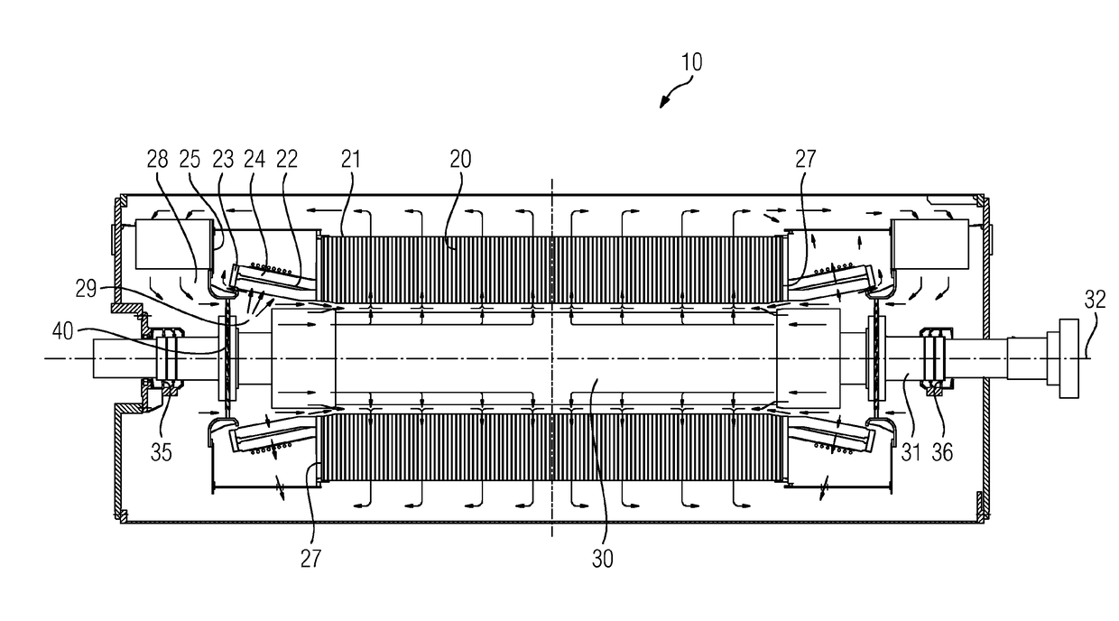
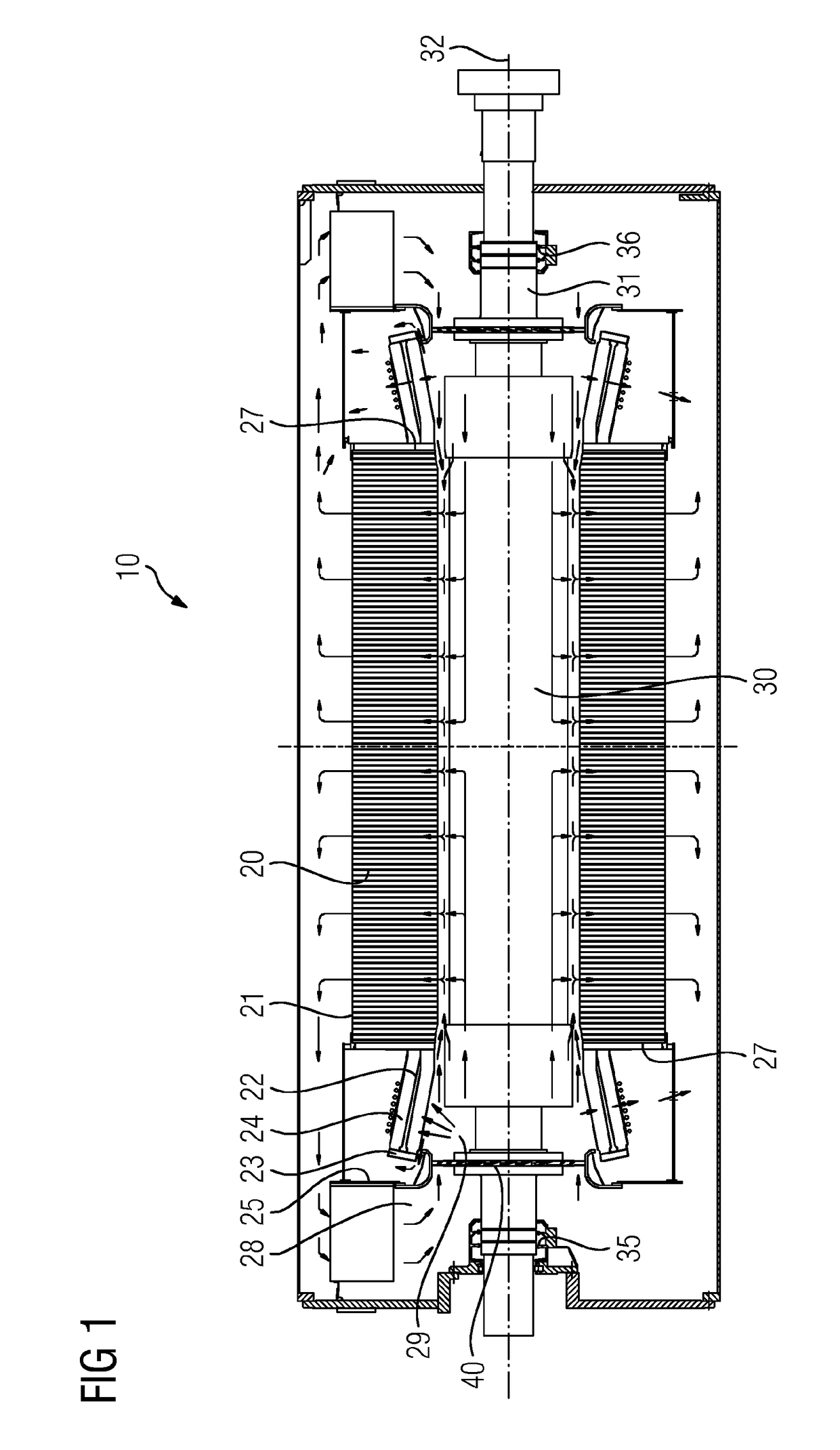
[0028]FIG. 1 shows a generator 10 for a power plant. The generator has a stator 20 in which there is arranged a rotor 30. The rotor 30 has a drive shaft 31 which is rotatably mounted at two bearings 35, 36. A central axis 32 runs through the drive shaft 31 of the rotor 30. The stator 20 is shielded on both sides by dividers 25. The stator 20 has a stator body 21 from which current conductors 22 exit at the ends 27 and form an end winding 24. In order to connect the current conductors 22, brackets 23 are provided at the ends and connect two adjacent current conductors 22 to one another in the end winding 24.

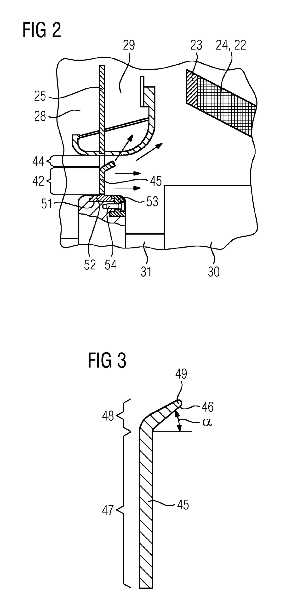
[0029]A fan 40 is attached to the rotor 30 and has, in the simple embodiment shown, fan blades 45 which are attached to the drive shaft 31 of the rotor, as shown in FIG. 2. The fan blades 45 are distributed evenly over the circumference of the drive shaft 31 and run in a plane with the divider 25 which laterally bounds the stator 20 and separates a suction side 28 of the fan 40 fr...


PUM


Abstract

A generator for a power plant and a method for cooling the generator, where the generator includes a stator and a rotor, the stator carrying conductors. The conductors for a winding overhang at least at one end of the stator and the generator has a fan for cooling the winding overhang. The fan produces a cooling air flow directed onto the winding overhang and has an axial component and a radial component.

Description

CROSS REFERENCE TO RELATED APPLICATIONS[0001]This application is the US National Stage of International Application No. PCT / EP2015 / 069606 filed Aug. 27, 2015, and claims the benefit thereof. The International Application claims the benefit of European Application No. EP14183928 filed Sep. 8, 2014. All of the applications are incorporated by reference herein in their entirety.FIELD OF INVENTION[0002]The present invention relates to a generator for a power plant, and to a method for cooling the generator.BACKGROUND OF INVENTION[0003]In turbo generators, the individual bars of the stator are connected by means of a so-called end winding. In the end winding, the bars are guided in both the tangential and the radial directions such that at the end of the end winding the bars that are to be connected lie next to one another. These bars must be electrically connected to one another, it being possible to effect the connection in various ways. One option is to connect the individual subcondu...

Claims


Application Information

Patent Timeline
Patent Type & Authority Applications(United States)
IPC IPC(8): H02K9/06H02K3/24H02K1/20H02K7/18
CPCH02K9/06H02K7/1807F04D29/384H02K1/20F04D19/002H02K3/24H02K9/08
Inventor BRAAM, JAN-HENRIKEVERS, CHRISTOPHGERTZ, SIMONGRAU SORARRAIN, ESTEBANHABERER, OLIVERHAGEDORN, MARKUSJAKEL, CHRISTIANKOEBE, MARIOKOWALSKI, MATTHIASMRKULIC, OMERMOLDERS, MARKUSSCHILD, CAROLIN
Owner SIEMENS AG
Learn More