
Laminated ceramic chip component including NANO thin film layer, manufacturing method therefor, and atomic layer vapor deposition apparatus therefor

a technology of nano thin film layer and laminated ceramic chip, which is applied in the manufacture of capacitors, final products, fixed capacitors, etc., can solve the problems of difficult fixation, inconvenient atomic layer deposition apparatus for forming nano thin film layer, and inability to easily separate laminated ceramic capacitors from mounting nozzles

Active Publication Date: 2017-09-14
HONGIK UNIV IND ACAD COOP FOUND +1
View PDF6 Cites 5 Cited by
  • Summary
  • Abstract
  • Description
  • Claims
  • Application Information

AI Technical Summary

Benefits of technology

The present invention provides a laminated ceramic chip component with a nano thin film layer and a method for manufacturing the same. The nano thin film layer is formed on the external electrode part which is in contact with the mounting nozzle, making it easy to separate from the mounting nozzle during manufacturing. The nano thin film layer is also easily moved when the chip component is surface-mounted to a circuit substrate, and can be formed on small-sized components such as laminated ceramic capacitors. The atomic layer deposition apparatus can create the nano thin film layer on the surface of small-sized components in a large amount.

Problems solved by technology

Therefore, even if the vacuum pressure is removed to mount the laminated ceramic capacitor on the circuit board after the laminated ceramic capacitor is transferred to the circuit board by the mounting nozzle, the laminated ceramic capacitor is not easily separated from the mounting nozzle.
Therefore, the conventional atomic layer deposition apparatus is not suitable for forming the nano thin film layer on a surface of component such as the laminated ceramic chip component which has a small size making it difficult to fix itself.

Method used


Image

  • Laminated ceramic chip component including NANO thin film layer, manufacturing method therefor, and atomic layer vapor deposition apparatus therefor
  • Laminated ceramic chip component including NANO thin film layer, manufacturing method therefor, and atomic layer vapor deposition apparatus therefor
  • Laminated ceramic chip component including NANO thin film layer, manufacturing method therefor, and atomic layer vapor deposition apparatus therefor

Examples


Embodiment Construction

[0042]Hereinafter, a laminated ceramic chip component provided with a nano thin film layer, a method for manufacturing the same and an atomic layer deposition apparatus therefor according to the present disclosure are described in detail with reference to the accompanying drawings.

[0043]First of all, a laminated ceramic chip component provided with a nano thin film layer according to one embodiment of the present disclosure is described.

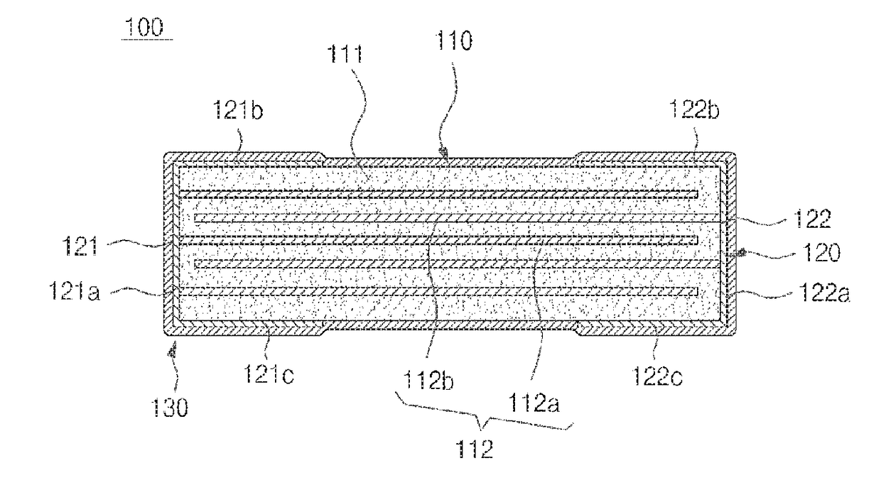
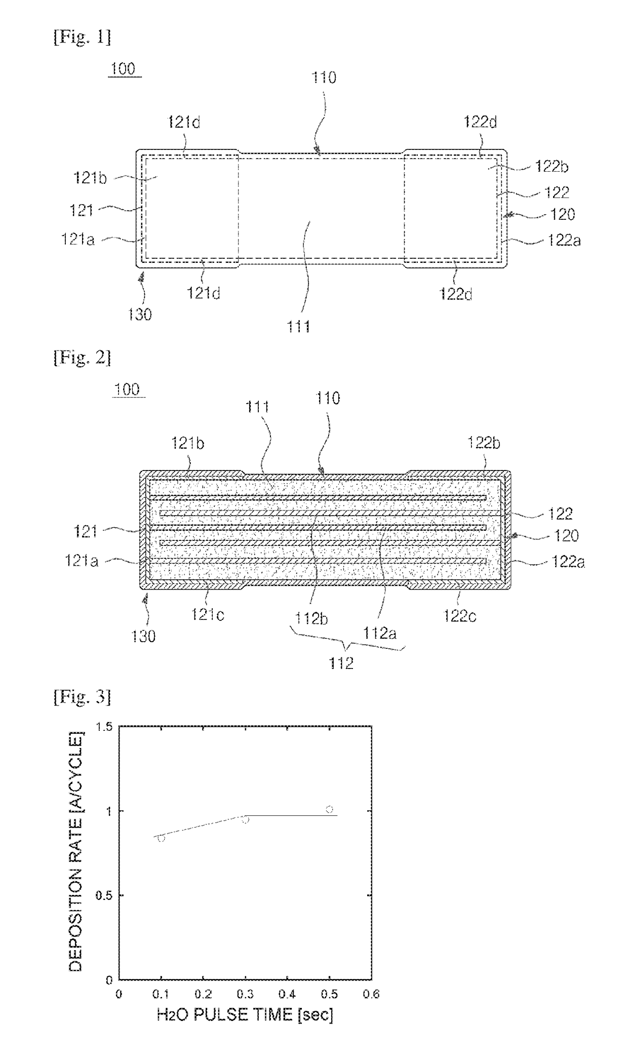
[0044]FIG. 1 is a plane view of a laminated ceramic capacitor provided with a nano thin film layer according to one embodiment of the present disclosure. FIG. 2 is a vertical sectional view taken along the line A-A in FIG. 1.

[0045]Referring to FIG. 1 and FIG. 2, a laminated ceramic chip component 100 according to one embodiment of the present disclosure is formed to include an element part 110, an external electrode part 120 and a nano thin film layer 130. The laminated ceramic chip component 100 is formed to have an approximately rectangular paralle...


PUM

PropertyMeasurementUnit
Temperatureaaaaaaaaaa
Timeaaaaaaaaaa

Abstract

The present disclosure discloses the laminated ceramic chimp component including an element part having a ceramic main body and an internal electrode placed in the ceramic main body; an external electrode part having a first external electrode and a second external electrode, the first and second external electrodes being provided with side electrodes covering both side surfaces of the ceramic main body, respectively, upper electrodes covering portions of both sides of an upper surface of the ceramic main body, respectively, and lower electrodes covering portions of both sides of a lower surface of the ceramic main body, respectively; and a nano thin film layer formed of electric insulation material and applied to a region including the upper electrodes, the method for manufacturing the same and the atomic layer deposition apparatus for the same.

Description

TECHNICAL FIELD[0001]The present disclosure relates to a laminated ceramic chip component including a nano thin film layer, a manufacturing method therefor and an atomic layer deposition apparatus therefor.BACKGROUND ART[0002]A laminated ceramic chip component is a chip component in which a plurality of ceramic layers are stacked and electrodes are arranged, components such as a laminated ceramic capacitor, a laminated chip inductor, a laminated power inductor or a laminated chip bead may be referred to as the laminated ceramic chip component.[0003]The laminated ceramic capacitor is formed in an approximately rectangular parallelepiped shape and includes an element part and electrode parts formed at both sides of the element part with respect to a widthwise direction. The element part is located at a center portion with respect to the widthwise direction when viewed from an upper surface of the laminated ceramic capacitor, and the electrode parts are located at both sides of the ele...

Claims


Application Information

Patent Timeline
IPC IPC(8): B82B3/00H01G4/232H01G4/30C23C16/46H05K3/34C23C16/455C23C16/458H01G4/005H01G4/33
CPCB82B3/0009B32B37/00H01G4/005H01G4/232H01G4/30H01G4/33H05K3/3442C23C16/45561C23C16/458C23C16/46H05K2201/10636H01G13/00B32B2037/246B32B2307/20B32B18/00B82B3/008C23C16/403C23C16/45544C23C16/45555C04B2237/34C04B2237/341C04B2237/343C04B2237/345C04B2237/348C04B2237/366C04B2237/368C04B2237/704H01G13/006H01G4/12H01G4/2325Y02P70/50
Inventor HWANG, JIN HAPARK, DAE BUMCHOO, YONG JOKIM, HYUN SUKPARK, DA HEEKO, MYEONG HEEKWON, KYOUNG WOOHWANG, HEE SUCHOI, JEONG WAN
Owner HONGIK UNIV IND ACAD COOP FOUND
Learn More