
Illumination apparatus

Active Publication Date: 2017-09-14
TOYOTA BOSHOKU KK
View PDF3 Cites 11 Cited by
  • Summary
  • Abstract
  • Description
  • Claims
  • Application Information

AI Technical Summary

Benefits of technology

The illumination apparatus described in this patent provides efficient use of light emitted from optical fibers, allowing for flexibility in design and space saving. By controlling the weaving method and positioning the light sources, the light emitting parts can be placed around the woven fabric, adding a new function to articles made with woven fabric. Additionally, using side-emitting optical fibers and allocating multiple exposure points to a single end part support creates a more designable and dressing effect. Furthermore, forming groove parts in the end part support maintains alignment between the exposed parts, resulting in a stable and efficient illumination.

Problems solved by technology

In fact, however, the conventional illumination apparatus described above has not utilized light propagated to the terminal ends of the optical fibers.
Further, it is possible to increase the number of the emitting parts without increasing the number of the light sources or to reduce the number of the light sources which have conventionally been required, leading to space saving and cost reduction.

Method used


Image

  • Illumination apparatus
  • Illumination apparatus
  • Illumination apparatus

Examples


example 1

(1-1) Configuration of Illumination Apparatus

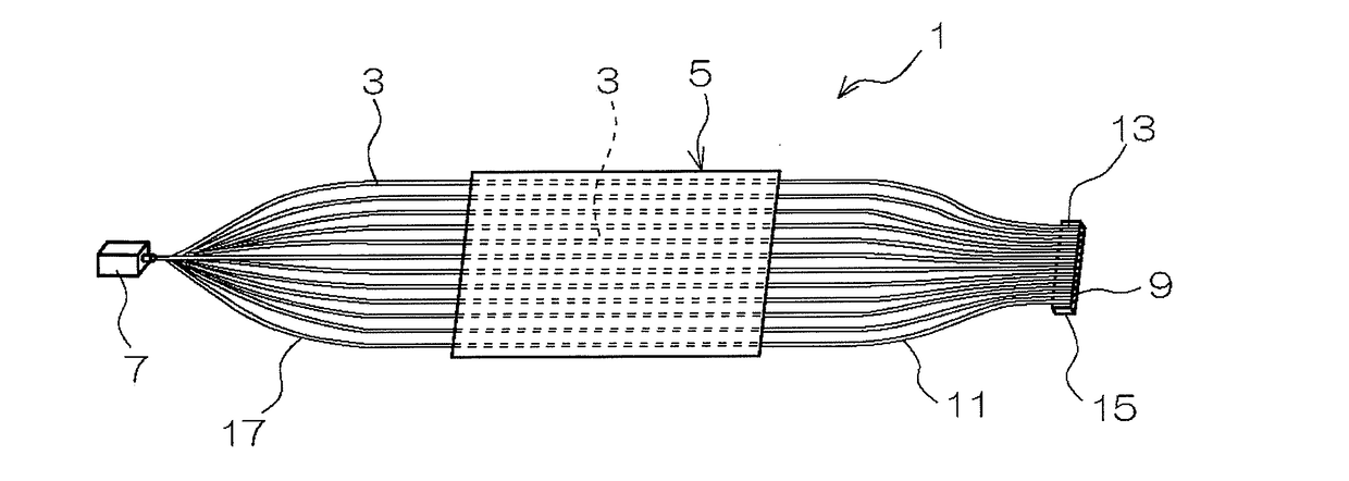
[0057]The illumination apparatus 1 of the present invention includes a woven fabric 5 and a light source 7 (LED light source), as shown in FIG. 1.

[0058]The woven fabric 5 is formed of warps [filaments made of polyester (not shown) and wefts [side-emitting optical fibers 3 and filaments made of polyester (not shown)].

[0059]One end side of the optical fibers 3 is exposed from the woven fabric 5 to constitute exposed parts 17 on one end side, and the tip ends of the plurality of exposed parts 17 on one end side are freely attachably / detachably coupled to the light source 7 in a state where the tip ends are bundled together.

[0060]The other end side of the optical fibers 3 is exposed from the woven fabric 5 to constitute exposed parts 11 on the other end side, and end parts 13 of the plurality of exposed parts 11 on the other end side are supported by an end part support 15.

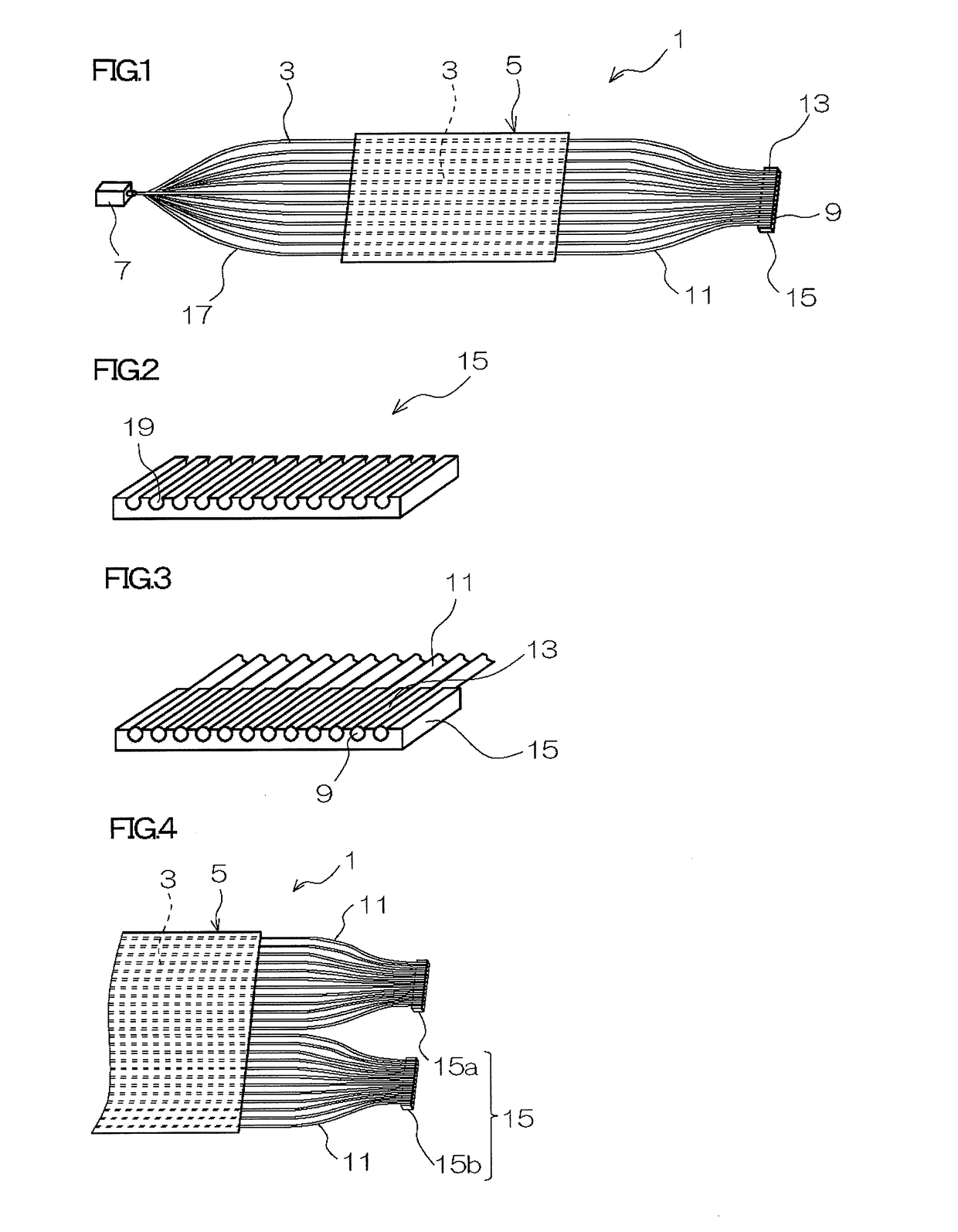
[0061]As shown in FIGS. 2 and 3, the end part support 15 is formed in ...

example 2

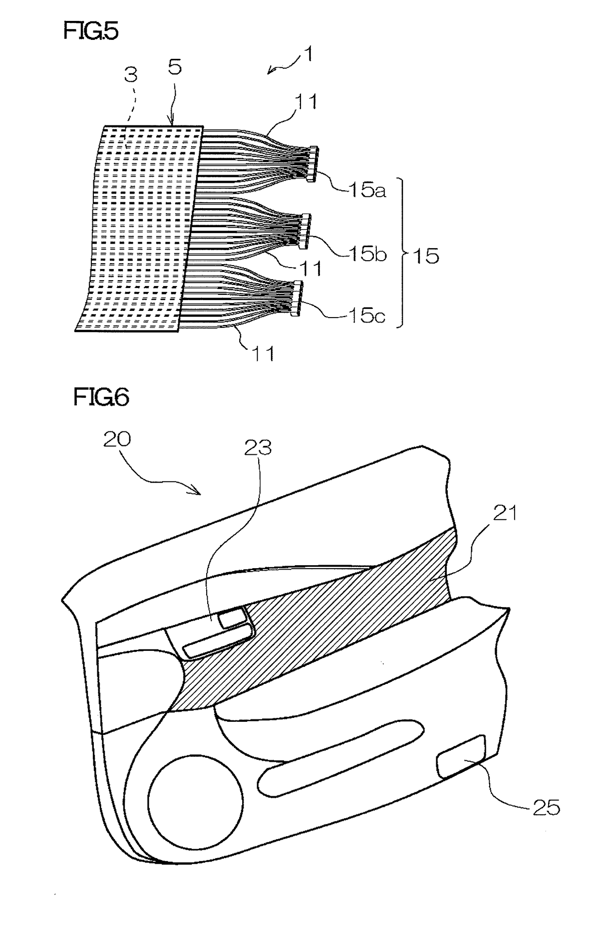
[0066]As Example 2, there will be described an example in which the illumination apparatus 1 of Example 1 given above [note that this illumination apparatus 1 includes two end part supports 15 (see FIG. 4)] is applied to a door trim for automobiles (see FIG. 6).

(2-1) Configuration of Door Trim

[0067]In a door trim 20 in FIG. 6, the woven fabric 5 in the illumination apparatus 1 of Example 1 (see FIG. 1) is disposed as a skin material for a door ornament 21, and two end part supports 15a, 15b (see FIG. 4) are disposed as light sources (light emission parts) of an inside handle lamp 23 and a courtesy lamp 25, respectively.

[0068]Incidentally, the light source 7, exposed parts 17 on one end side and exposed parts 11 on the other end side (see FIG. 1) in the illumination apparatus 1 of Example 1 are not shown.

(2-2) Action and Effect of Illumination Apparatus Applied to Door Trim

[0069]According to Example 2, light delivered from one light source 7 (see FIG. 1) is emitted from the end surfa...

example 3

[0071]As Example 3, there will be described an example in which the illumination apparatus 1 of Example 1 described above [note that this illumination apparatus 1 includes three end part supports 15 (see FIG. 5)] is applied to a roof trim for automobiles (see FIG. 7).

(3-1) Configuration of Roof Trim

[0072]In a roof trim 30 in FIG. 7, the woven fabric 5 in the illumination apparatus 1 of Example 1 (see FIG. 1) is disposed as a ceiling skin material 31, and three end part supports 15a, 15b, 15c (see FIG. 5) are disposed as light sources (light emission parts) of a front vanity lamp 33, a front map lamp 35 and a rear lamp 37, respectively.

[0073]Incidentally, the light source 7, exposed parts 17 on one end side and exposed parts 11 on the other end side (see FIG. 1) in the illumination apparatus 1 of Example 1 are not shown.

(3-2) Action and Effect of Illumination Apparatus in Roof Trim

[0074]According to Example 3, light delivered from one light source 7 (see FIG. 1) is emitted from the e...


PUM

PropertyMeasurementUnit
Lengthaaaaaaaaaa

Abstract

An illumination apparatus includes a woven fabric in which optical fibers are woven as a constituent yarn and a light source. The illumination apparatus makes light delivered from the light source incident upon the end surfaces on one end side of the optical fibers and emits the light at least from the end surfaces on the other end side of the optical fibers for illumination. The other end side of the optical fibers is exposed from the woven fabric to constitute exposed parts, and the end parts of a plurality of the exposed parts on the other end side are supported by an end part support to form emitting parts which emit light from the light source. On the end part support, the end parts of the exposed parts on the other end side are individually supported such that their respective end surfaces are aligned on the same plane.

Description

CROSS-REFERENCE TO RELATED APPLICATIONS[0001]The present application claims priority under 35 U.S.C. §119 of Japanese Application No. 2016-46221 filed on Mar. 9, 2016, the disclosure of which is expressly incorporated by reference herein in its entirety.BACKGROUNDTechnical Field[0002]The present invention relates to an illumination apparatus. More specifically, the invention relates to an illumination apparatus which utilizes light emitted from the end parts of optical fibers used as a constituent yarn for a woven fabric.Related Art[0003]As an illumination apparatus utilizing optical fibers, there has conventionally been proposed an optical fiber illumination apparatus including a light source and an optical fiber woven fabric in which optical fibers are regularly woven between normal yarns at predetermined intervals, wherein, upon incidence of light into the optical fibers, the optical fiber woven fabric functions as an illumination apparatus (see JP 2910-267573 A).SUMMARY[0004]In ...

Claims


Application Information

Patent Timeline
IPC IPC(8): F21V8/00D03D25/00D03D1/00
CPCG02B6/001G02B6/0008D03D1/0088D03D25/00B60Q2500/10F21V33/0012F21W2131/301B60Q3/64B60Q3/54D10B2401/20B60Q3/217B60Q3/745D03D15/547D03D15/283
Inventor YAMADA, TAKAMASACHAZA, SEIJIOKAHARA, SHINGOSAKOH, MITSUTAKAKANAMORI, HIDEOITO, ATSUHIKO
Owner TOYOTA BOSHOKU KK
Learn More