Motor drive device

a technology of motor drive and drive shaft, which is applied in the direction of electric devices, battery/fuel cell control arrangements, electric devices, etc., can solve the problems of increasing the cost, damage, degradation and damage of the circuit elements or each device,

Active Publication Date: 2017-09-14
MITSUBISHI ELECTRIC CORP
View PDF9 Cites 14 Cited by
  • Summary
  • Abstract
  • Description
  • Claims
  • Application Information

AI Technical Summary

Benefits of technology

[0010]The present invention has been made in order to solve the above-mentioned problems, and has an object to obtain a motor drive device configured to switch to three-phase short circuit or all-phase shut off in advance so as to prevent overvoltage instead of switching the control after overvoltage is determined, thereby enabling a DC power supply device and an inverter to be protected.
[0012]According to the motor drive device of the present invention, the control to be performed in the inverter is switched between the all-phase shut off and the three-phase short circuit based on a motor rotation speed or a induced voltage of the motor when it is determined that at least one of the inverter or the DC power supply device has a failure, and current is inhibited from flowing from the motor to the DC power supply device. Thus, the control can be switched between the three-phase short circuit and the all-phase shut off in advance so as to prevent overvoltage instead of switching the control after overvoltage is determined, with the result that the DC power supply device and the inverter can be protected.

Problems solved by technology

As a result, a large overvoltage occurs due to the voltage increase, and this overvoltage is applied to circuit elements in the motor drive device, such as smoothing capacitors, or is applied to each device connected to the motor drive device as a load of a DC power supply, to thereby cause troubles such as degradation and damage of the circuit elements or each device.
However, it is concerned that when the electric power conversion device is controlled to establish the phase short-circuit state after overvoltage is determined as in Japanese Patent No. 4675299 described above, time elapses in the overvoltage state, and hence the circuit elements used in the control device or the loads of the rotating electric machine cannot be protected from degradation, damage, and the like that are caused due to overvoltage during that time.
Further, the overvoltage determination processing may be complicated and may lead to an increase in cost.
However, current is inhibited from flowing to the power supply side in some cases because, for example, a power supply has a failure or a battery is fully charged.

Method used


Image

  • Motor drive device
  • Motor drive device
  • Motor drive device

Examples


first embodiment

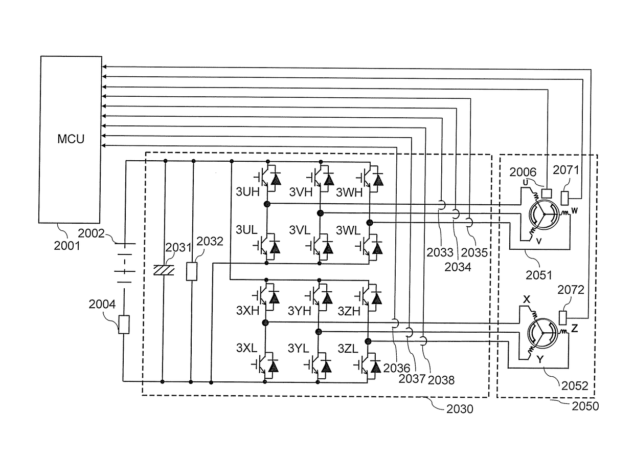
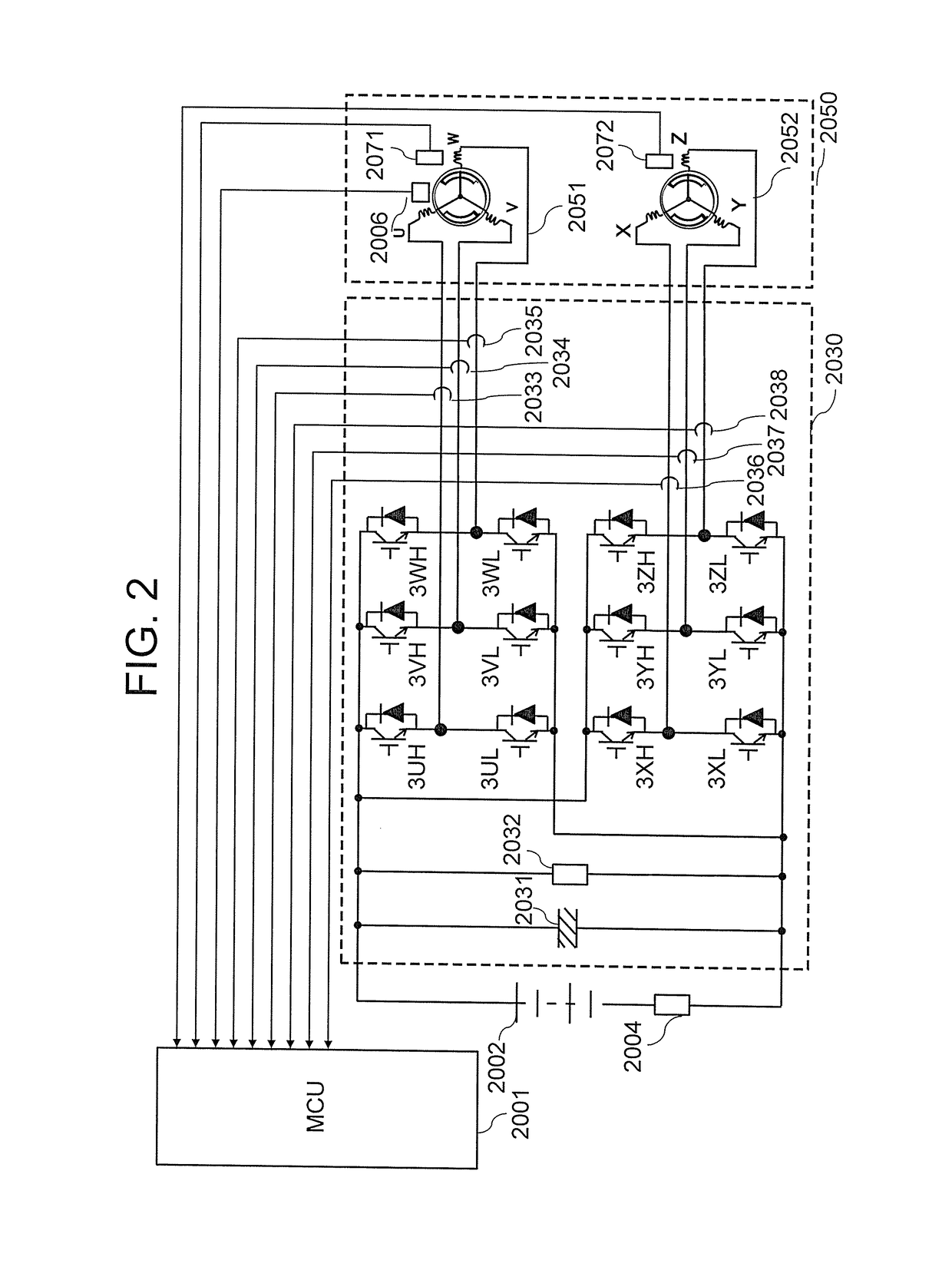
[0041]FIG. 3 is a flow chart of processing of determining whether to permit or prohibit the PWM control in the motor drive device according to the first embodiment of the present invention. That is, the MCU 2001 determines, in accordance with the processing flow of FIG. 3, whether or not to allow the double three-phase inverter 2030 to perform the PWM control. The MCU 2001 includes a memory (not shown), and has a PWM permission / prohibition flag stored in the memory. The MCU 2001 sets the PWM permission / prohibition flag stored in the memory to “permission” or “prohibition” based on a result of determination made in the flow of FIG. 3. The processing flow of FIG. 3 is performed by a failure determination unit (not shown) provided in the MCU 2001. The processing is described in detail below.

[0042]First, in Step S3001, the MCU 2001 determines whether the double three-phase inverter 2030 has a failure. As the failure of the double three-phase inverter 2030, for example, the following are...

second embodiment

[0078]FIG. 5 is a flow chart of processing of switching among the all-phase shut off, the three-phase short circuit, and the PWM based on respective conditions, and performing the switched-to control in a motor drive device according to a second embodiment of the present invention. The processing flow of FIG. 5 is performed by a switching unit (not shown) provided in the MCU 2001. The remaining configuration and operation are the same as those of the first embodiment.

[0079]In FIG. 5, Steps S5001, S5002, S5004, S5101, and S5201 are the same as Steps S4001, S4002, S4004, S4101, and S4201 of FIG. 4, respectively, and hence the description thereof is herein omitted.

[0080]In this embodiment, in Step S5003, the MCU 2001 determines whether an induced voltage of the double three-phase motor 2050 is equal to or less than a threshold 2 set in advance. When the induced voltage is not equal to or less than the threshold 2, the MCU 2001 proceeds to Step S5101 to perform processing for the three-...

third embodiment

[0084]FIG. 6 is a flow chart of processing of switching to the all-phase shut off, the three-phase short circuit, and the PWM based on respective conditions, and performing the switched-to control in a motor drive device of a vehicle according to a third embodiment of the present invention. The processing flow of FIG. 6 is performed by a switching unit (not shown) provided in the MCU 2001. The remaining configuration and operation are the same as those of the first embodiment or the second embodiment described above.

[0085]In FIG. 6, Steps S6001, S6002, S6004, S6101, and S6201 are the same as Steps S4001, S4002, S4004, S4101, and S4201 of FIG. 4, respectively, and hence the description thereof is herein omitted.

[0086]In this embodiment, in Step S6003, the MCU 2001 obtains an estimated induced voltage of the double three-phase motor 2050, and determines whether the estimated induced voltage is equal to or less than a threshold 3 set in advance. When the estimated induced voltage is no...


PUM


Abstract

MCU (2001) determines whether at least one of double three-phase inverter (2030) or battery (2002) has a failure, or battery (2002) is fully charged, and switches control to be performed in inverter (2030) between all-phase shut off and three-phase short circuit based on a motor rotation speed of double three-phase motor (2050) when MCU (2001) determines that any one of inverter (2030) and battery (2002) has a failure, or battery (2002) is fully charged. Battery (2002) and inverter (2030) can be protected when current is inhibited from flowing from motor (2050) to battery (2002) due to a failure of inverter (2030) or battery (2002).

Description

BACKGROUND OF THE INVENTION[0001]1. Field of the Invention[0002]The present invention relates to a motor drive device, and more particularly, to a motor drive device configured to selectively switch between three-phase short circuit and all-phase shut off based on a motor rotation speed or an induced voltage of a motor.[0003]2. Description of the Related Art[0004]In recent years, attention has been paid on a hybrid vehicle and an electric vehicle as energy-saving and environmentally friendly vehicles. The hybrid vehicle uses a motor as well as a conventional engine as power sources, and the electric vehicle uses a motor as a power source. The hybrid vehicle and the electric vehicle are both configured so that DC electric power stored in a battery is converted into AC electric power by an inverter circuit to drive a motor and run the vehicle.[0005]Further, the hybrid vehicle includes a motor-generator having a power generation function. The motor-generator is configured to generate p...

Claims


Application Information

Patent Timeline
Patent Type & Authority Applications(United States)
IPC IPC(8): H02P27/08B60W10/08B60L11/18B60W20/10H02P6/08H02H7/08B60L50/10B60L50/15
CPCH02P27/08H02P6/08H02H7/0833B60L11/1803Y10S903/906B60W20/10B60W10/08B60L2210/30B60L2210/40B60L11/1861B60L50/10B60L3/003B60L3/0046H02P25/22H02P3/22H02P29/032B60L50/51B60L58/12H02P29/0241H02H7/1225B60W20/50Y02T10/62Y02T10/64Y02T10/70Y02T10/72B60L7/003
Inventor MURATA, YASUKAZUENOKI, KEIICHIWATANABE, MASUTAKAHARADA, SHINGONISHIJIMA, YOSHIMASA
Owner MITSUBISHI ELECTRIC CORP
Why Eureka
Try Eureka