

Lighting apparatus with a variable light beam emission angle
- Summary
- Abstract
- Description
- Claims
- Application Information
AI Technical Summary
Benefits of technology
Problems solved by technology
Method used
Image

Examples
Embodiment Construction
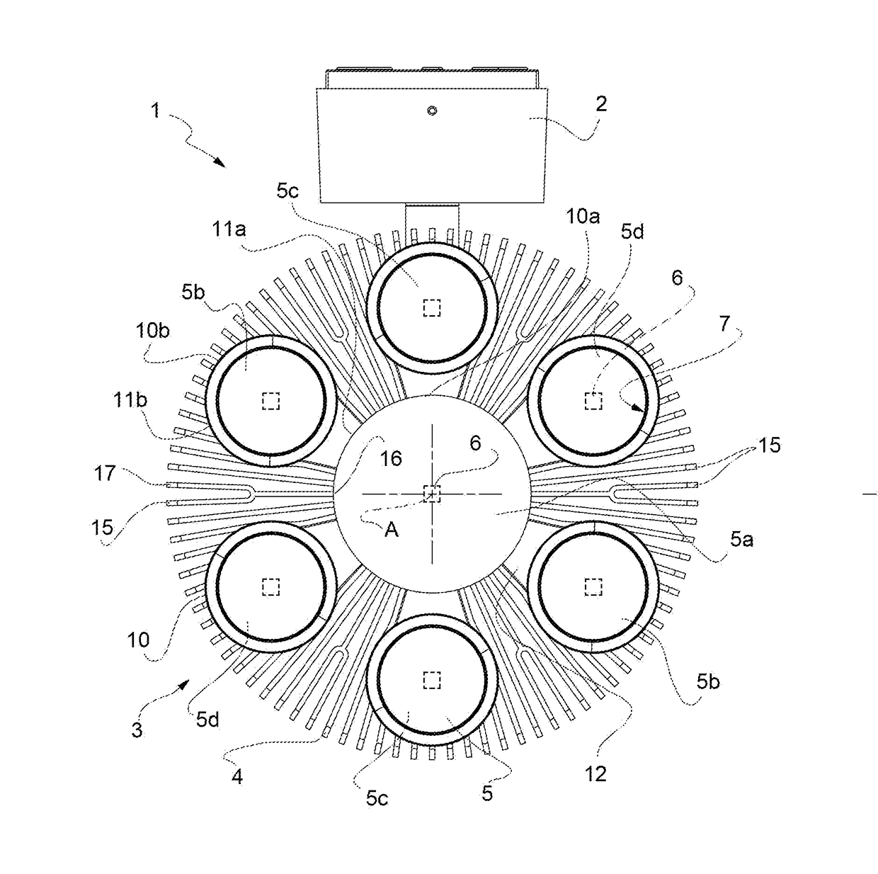
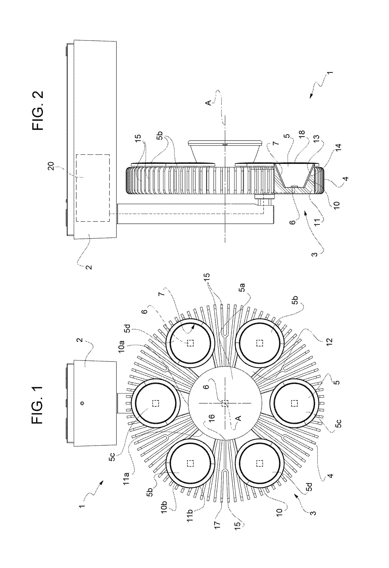
[0014]In FIGS. 1 and 2, the numeral 1 indicates, as a whole, a lighting apparatus with a variable light beam emission angle capable of emitting light beams having different amplitudes (emission angles).
[0015]The apparatus 1 comprises a support structure 2 and a lighting head 3 supported by the support structure 2.
[0016]The support structure 2 may take various shapes, also depending on the intended purpose of the apparatus 1 (which may serve as a swinging lamp, a wall lamp, a recessed lamp, etc.). Optionally, the support structure 2 includes articulations and / or joints in order to allow the position or orientation of the lighting head 3 to be varied.
[0017]The lighting head 3 comprises a base body 4 and a plurality of optical groups 5 mounted on the base body 4: each optical group 5 comprises a light source 6 and a dedicated optical system 7 acting exclusively on the light emitted by that same light source 6.
[0018]The base body 4 extends along a longitudinal axis A.
[0019]In the illust...
PUM
 Abstract
Description
Claims
Application Information