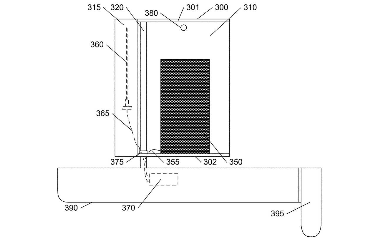
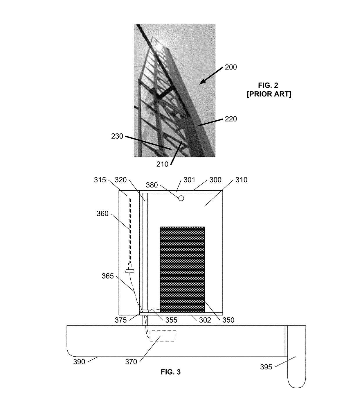
Housing electrical components in a translucent wingsail

a technology of electrical components and translucent wingsails, which is applied in the direction of special-purpose vessels, vessel construction, marine propulsion, etc., can solve the problems of reducing the differential between the leeward and windward sides of the wingsail, limiting the output energy of introducing drag over the sails and the vessel, so as to enhance the performance of solar panels and antennas, enhance the visibility of other vessels, and enhance the lift-to-drag ratio

Active Publication Date: 2017-09-21
MARINE ROBOTICS LLC
View PDF7 Cites 3 Cited by
  • Summary
  • Abstract
  • Description
  • Claims
  • Application Information

AI Technical Summary

Benefits of technology

[0012]It would be advantageous to provide a sailing vessel that provides a high lift-to-drag ratio. It would also be advantageous to provide a sailing vessel that provides environmental protection to electrical components, such as solar panels, so that the solar panel itself need not include a protective exterior.
[0013]These advantages, and others, can be realized by creating a substantially hollow wingsail that is configured to enable electrical components, or other components to be situated within the wingsail. In particular, the wingsail may be configured to contain the solar p...

Problems solved by technology

Additionally, solar panels that are situated on the surface of the sailing vessel are often shadowed by the sails, which substantially limits their output energy.
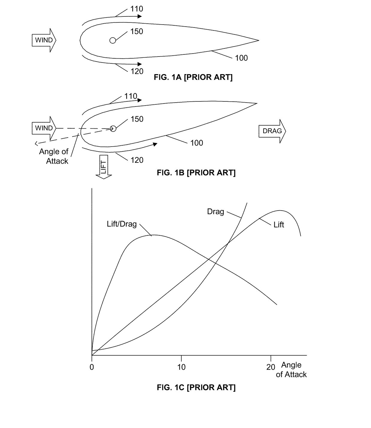
However, the flow of wind over the sails and the vessel introduces drag, parallel to the wind direction.
If the angle of attack is further increased, the airflow on the leeward side of the wingsail will ‘separate’ from the wingsai...

Method used


Image

  • Housing electrical components in a translucent wingsail
  • Housing electrical components in a translucent wingsail
  • Housing electrical components in a translucent wingsail

Examples


Embodiment Construction

[0020]In the following description, for purposes of explanation rather than limitation, specific details are set forth such as the particular architecture, interfaces, techniques, etc., in order to provide a thorough understanding of the concepts of the invention. However, it will be apparent to those skilled in the art that the present invention may be practiced in other embodiments, which depart from these specific details. In like manner, the text of this description is directed to the example embodiments as illustrated in the Figures, and is not intended to limit the claimed invention beyond the limits expressly included in the claims. For purposes of simplicity and clarity, detailed descriptions of well-known devices, circuits, and methods are omitted so as not to obscure the description of the present invention with unnecessary detail.

[0021]The term translucent as used herein is consistent with the term as defined in the Merriam-Webster dictionary: “Translucent: permitting the...


PUM


Abstract

A substantially hollow wingsail is configured to enable electrical components to be situated within the wingsail. In particular, the wingsail may be configured to contain the solar panels used to power the other electrical components of the vessel, as well as other items that are conventionally situated on the exterior of the vessel, such as antennas, navigation lights, and so on. The surface of the wingsail may include transparent or translucent areas to provide light to the solar panels, as well as optical and electromagnetic reflective areas within the wingsail to enhance the performance of the solar panels and antennas. The wingsail may also include an internal light that illuminates the translucent areas of the wingsail for enhanced visibility to other vessels.

Description

[0001]This application claims the benefit of U.S. Provisional Patent Application 62 / 308,519, filed 15 Mar. 2016.BACKGROUND AND SUMMARY OF THE INVENTION[0002]This invention relates to the field of autonomous sailing, and in particular to mounting electrical components, such as solar panels, within a transparent wing sail.[0003]The interest and advancements in autonomous sailing vessels are continually increasing. As disclosed in U.S. Pat. No. 8,973,511, “AUTONOMOUS SAILBOAT FOR OCEANOGRAPHIC MONITORING”, issued 10 Mar. 2015 to Walter Holemans and incorporated by reference herein, fleets of such autonomous sailing vessels may be used to monitor oceanographic environmental conditions, engage in search and rescue operations, report on potential pirate activities, and so on.[0004]Such autonomous sailing vessels may include numerous electrical devices to provide navigation, communication, monitoring, auxiliary propulsion, and so on. Conventionally, solar panels are deployed on an outer su...

Claims


Application Information

Patent Timeline
IPC IPC(8): B63H9/06H02S40/22H02S10/40B63B35/00B63B45/04
CPCB63H9/0607B63H9/0657B63B35/00B63B45/04H02S10/40B63J2099/006B63B2201/20B63B2201/08B63B2209/18B63B2035/009H02S40/22B63B2035/4453B63H9/061B63H9/067H02S20/30Y02E10/52Y02E10/60H02S30/20H02S40/44
Inventor VANDYCK, VINCENTHOLEMANS, WALTER
Owner MARINE ROBOTICS LLC
Why Eureka
Try Eureka