

Cell mass culture vessel
a cell aggregate and culture vessel technology, applied in the field of cell aggregate culture vessels, can solve the problems of low success rate of embryonic body formation, inability to observe microscopically, human es cells have problems of a higher possibility of cell death, and a greater difficulty in obtaining embryonic bodies, and achieve the effect of efficient exchang
- Summary
- Abstract
- Description
- Claims
- Application Information
AI Technical Summary
Benefits of technology
Problems solved by technology
Method used
Image

Examples
embodiment 1
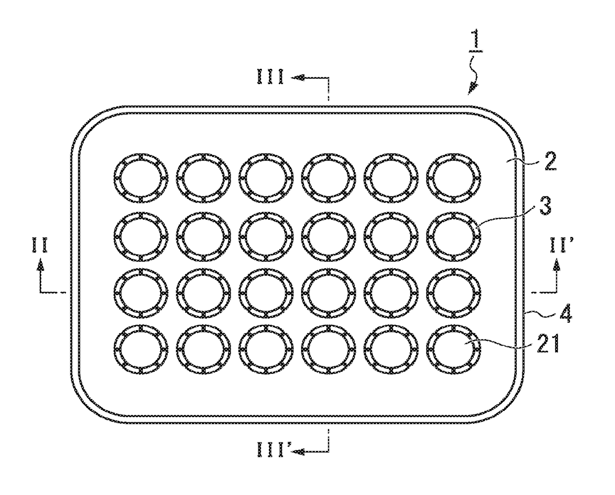
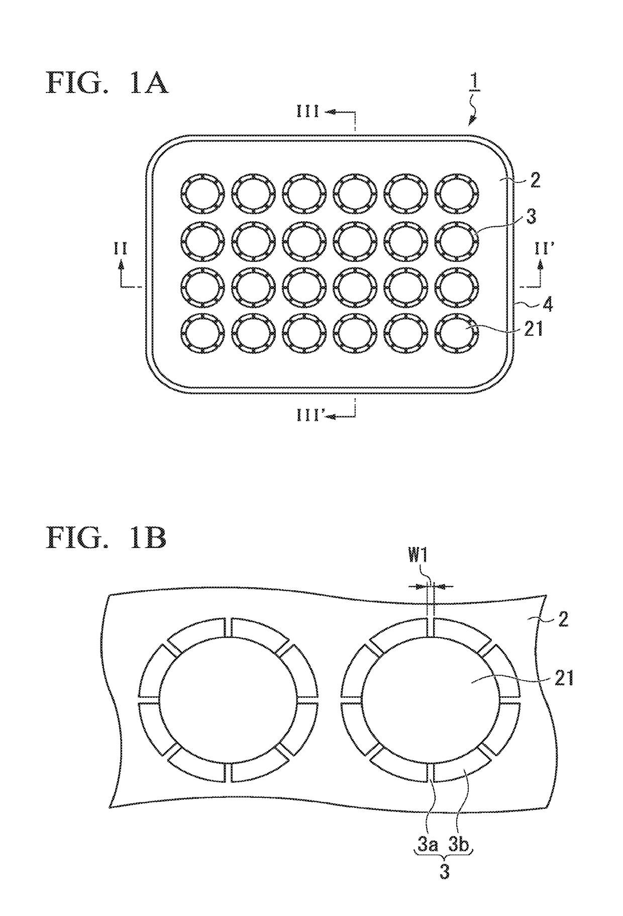
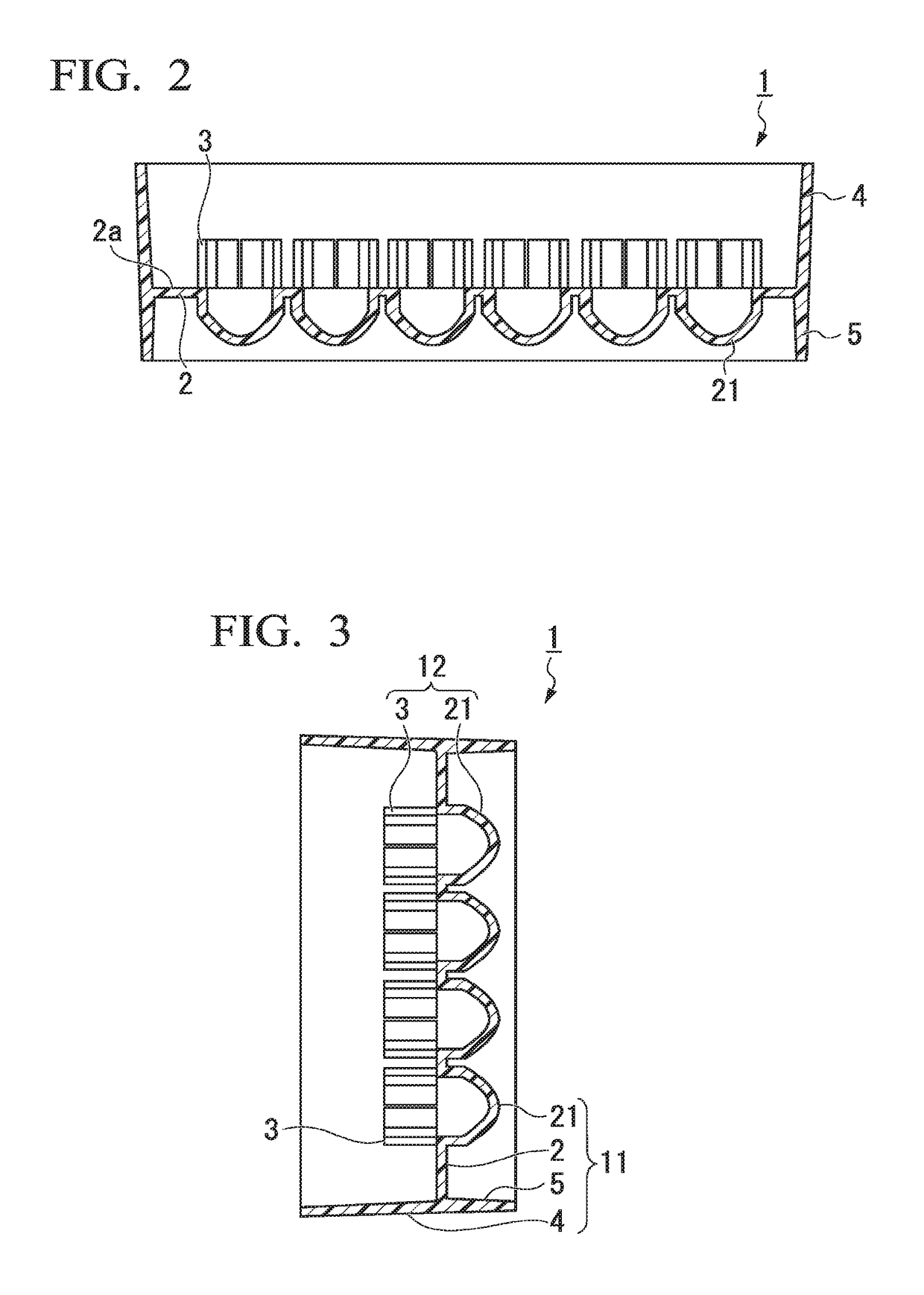
[0099]FIG. 1A is a plan view of a cell aggregate culture vessel of Embodiment 1, and FIG. 1B is a partial enlarged view of FIG. 1A. FIG. 2 is a sectional view in the direction of arrow line II-II′ in FIG. 1A, FIG. 3 is a sectional view in the direction of arrow line in FIG. 1A, and FIG. 4 is a partial enlarged view of FIG. 2.
[0100]A culture vessel 1 of Embodiment 1 which will be described using FIGS. 1A to 4 is a vessel for culturing cell aggregates. The culture vessel 1 includes a plurality of wells 21 formed in a plate-like body 2 and tubular bodies 3 disposed above the respective wells 21. For convenience, a direction intersecting the plane of the plate-like body 2 at right angles will be referred to as the “vertical direction”, the tubular body 3 side will be referred to as being “above”, and the well 21 side will be referred to as being “below”.
[0101]The culture vessel 1 of Embodiment 1 includes a side wall 4 which protrudes above openings of a plurality of the wells 21 and sur...
embodiment 2
[0147]FIG. 5 is a plan view of a cell aggregate culture vessel 6 of Embodiment 2. FIG. 6 is a sectional view in the direction of arrow line VI-VI′ in FIG. 5. FIG. 7 is an enlarged end view cut in the direction of arrow line VII-VII′ in FIG. 5. FIG. 8 is a plan view of a multi-well plate body 61 constituting the cell aggregate culture vessel 6 of Embodiment 2, and FIG. 9 is a sectional view in the direction of arrow line IX-IX′ in FIG. 8. FIG. 10 is a plan view of a liquid flow control body 800 constituting the cell aggregate culture vessel 6 of Embodiment 2, FIG. 11 is a bottom surface view of the liquid flow control body 800 illustrated in FIG. 10, FIG. 12 is an enlarged sectional view in the direction of arrow line XII-XII′ in FIG. 10, FIG. 13 is an enlarged side view of FIG. 10, and FIG. 14 is an enlarged perspective view of the liquid flow control body 800 illustrated in FIG. 11.
[0148]The culture vessel 6 of Embodiment 2 which will be described using FIGS. 5 to 14, similar to th...
embodiment 3
[0165]FIG. 15A is a plan view of a cell aggregate culture vessel 100 of Embodiment 3, FIG. 15B is a partial enlarged view of FIG. 15A. FIG. 16 is an enlarged sectional view in the direction of arrow line XVI-XVI′ in FIG. 15A. FIG. 17A is a sectional view in the direction of arrow line XVII-XVII′ in FIG. 15A, and FIG. 17B is a partial enlarged view of FIG. 17A. FIG. 18 is a partial enlarged view of FIG. 16, and FIG. 19 is a perspective sectional view for describing an internal structure of the structure 12 made up of the tubular body 3 and the well 21 of the cell aggregate culture vessel 100. FIG. 20 is a partial enlarged view of FIG. 15A, and FIG. 21 is a conceptual view for describing a state after a cell aggregate 14 is cultured in a culture fluid 13 for a predetermined time using the cell aggregate culture vessel 100 of the present disclosure and then some of the culture fluid 13 in the well 21 is discharged to the outside of the structure 12 through the communication portion 3a....
PUM
| Property | Measurement | Unit |
|---|---|---|
| Length | aaaaa | aaaaa |
| Angle | aaaaa | aaaaa |
| Angle | aaaaa | aaaaa |
Abstract
Description
Claims
Application Information