Pipe mount

a technology of pipe mounts and pipes, applied in couplings, soldering devices, auxilary welding devices, etc., can solve the problems of poor visibility, cramped work space, and time-consuming cutting-in operations to access pipes,

Active Publication Date: 2017-09-21
UPONOR INNOVATION AB
View PDF11 Cites 0 Cited by
  • Summary
  • Abstract
  • Description
  • Claims
  • Application Information

AI Technical Summary

Benefits of technology

[0031]The technical effect of the invention is that due to the pipe mount disclosed herein, pipe sections may be connected in a simple and time-saving manner while mounting plumbing arrangement elements in place. The prefabricated plumbing arrangement element may be configured in such a way that the installing personnel may not be able to reach some of the pipes inside it due to other pipes and their insulation being in the way. Therefore it is necessary to be able to move thus unreachable pipe section with a system that is preferably external to the plumbing arrangement element, in order for the installing personnel to be able to make all the necessary connections between pipe sections of two adjoining spaces.
[0032]The installation work that needs to be done above the plumbing arrangement element—completing different pipe connections, installing insulation, near the ceiling level is difficult due to the high location, lack of space leading to poor tool clearances and cramped work space, and poor visibility. All these factors may lead to installation error which, in turn, may lead to leaks or other problems later on.
[0033]The fittings enable fast and simple pipe connections to be completed without external tools, reducing and simplifying on site plumbing work and, at the same time, reducing risks of installation errors. Pre-insulated pipes can be extended all the way to a ceiling level, thus reducing the amount on insulation work needed on site.
[0034]The pipe mount may be arranged into a prefabricated plumbing arrangement element which comprises all the necessary pipe sections, their insulation and connecting points. On site installation time is reduced, the installing personnel need not worry about tolerances as much as with separate plumbing pieces, the installation surface area can be minimized and overall quality of water and sewage installation improved.
[0035]By lead-through herein is meant generally the connection or joint between two separate spaces one of which is located wholly or partially above the other, the connection extending from the ceiling of the space below to the floor level of the space above, and extending through the floor structure between the two spaces.
[0036]By pipeline and pipe herein is meant any extended conduit or conducting line, comprising several individual pieces of pipe connected to each other to form a conducting line, including but not limited to tap water pipes, grey water pipes and sewage pipes. The two terms pipe and pipeline may be used interchangeably throughout this disclosure.

Problems solved by technology

At the time renovations, when the water and sewage installations need to be replaced, costly and time-consuming cutting-in operations are needed to access the pipes.
These kinds of installations are time-consuming and require great precision from the persons conducting the installations, to avoid any mistakes that could lead to water or moisture damages within the sanitary space or building structures.
The current solutions, however, require a certain amount of skilled work in aligning the vertical lines of pipes and other conducting elements, leading them through the floor structures between two vertically adjoining sanitary spaces, and connecting the pipelines.
Especially when the on-site personnel is not used to working with such installation assemblies, problems may arise.
For example, aligning water pipes through floor structures may be challenging.
When installing the plumbing arrangement element, the personnel need to connect the pipes of two vertically adjoining spaces by supplying connecting pipe sections between the preinstalled pipes, accomplish all required connections and install other elements such as insulation and casings, often in very confined and ergonomically difficult spaces.

Method used


Image

  • Pipe mount
  • Pipe mount
  • Pipe mount

Examples


Embodiment Construction

[0043]The detailed description provided below in connection with the appended drawings is intended as a description of the present examples and is not intended to represent the only forms in which the present example may be constructed or utilized. However, the same or equivalent functions and sequences may be accomplished by different examples.

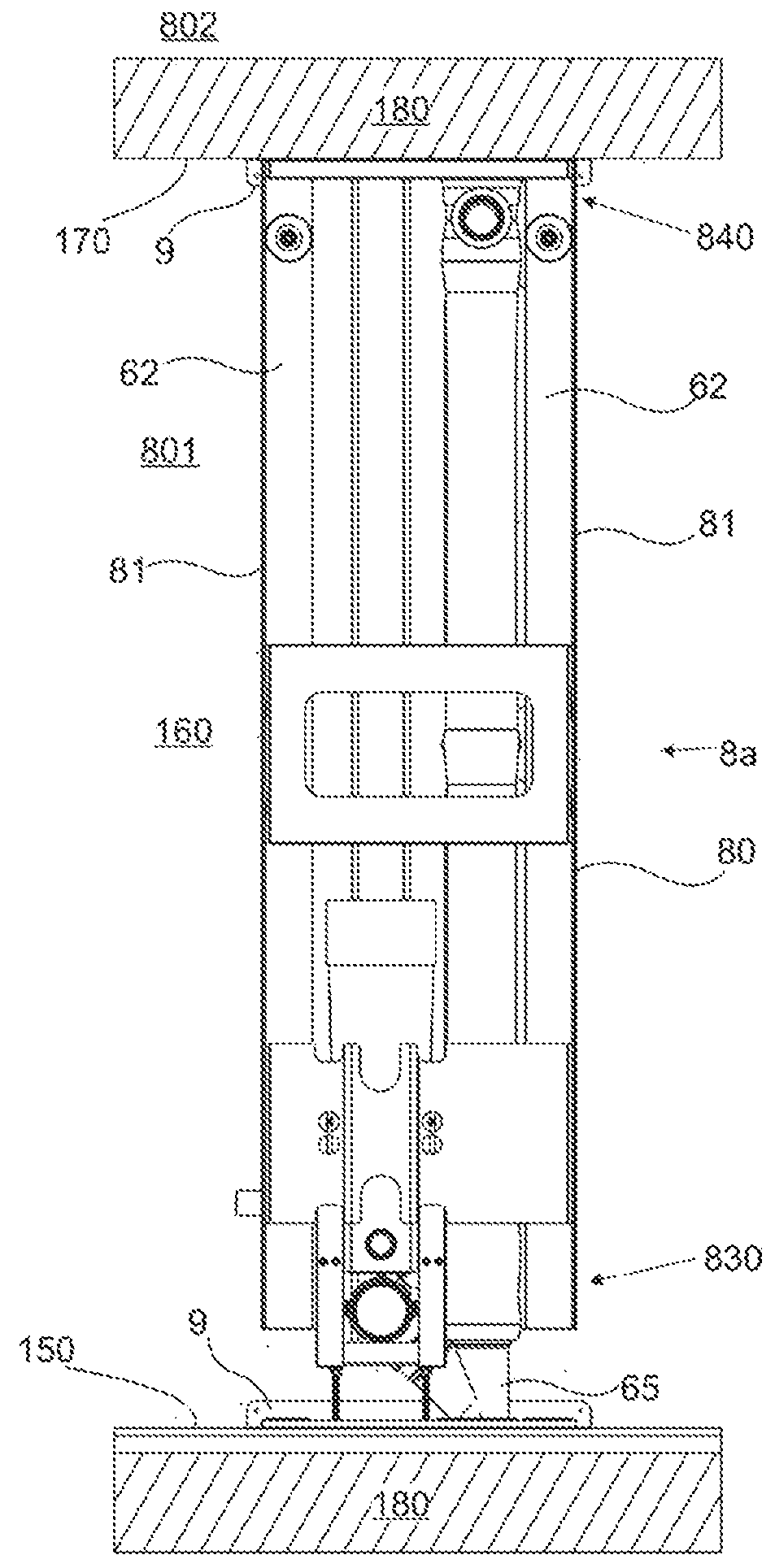
[0044]A plumbing arrangement element 8a in FIG. 1, shown as a front view, comprises a vertical support structure 80 having sidewalls 81, a back wall and a detachable front cover panel (the latter two are not shown in FIG. 1), all extending in the vertical direction of the space 801, i.e. from a floor 150 or the vicinity of the floor 150 towards a ceiling 170. The plumbing arrangement element 8a comprises a bottom part 830 disposed above and adjacent to a floor 150 of the space 801, and a top part 840 disposed below and adjacent to a ceiling 170 of the space 801.

[0045]The plumbing arrangement element 8a may have different pipe sections and con...


PUM


Abstract

A pipe mount for connecting pipe sections is disclosed. The pipe mount comprises a sliding member movably attached to a plumbing arrangement element. The sliding member extends in the vertical direction of the plumbing arrangement element, and it is vertically movable between an extreme position and a second position. The pipe mount further comprises at least one pipe bracket for securing the pipe sections onto the sliding member. A system and a method for connecting pipe sections are also disclosed.

Description

RELATED APPLICATION[0001]This application claims priority to European Application No. 16160460.8 filed on Mar. 15, 2016, the contents of which are hereby incorporated by referenced in their entirety.FIELD OF THE INVENTION[0002]The present invention relates generally to a pipe mount. In particular, the present invention relates to a spring-loaded pipe mount for connecting and installing water pipes in prefabricated plumbing arrangement elements to form a continuous vertical pipeline.BACKGROUND OF THE INVENTION[0003]Historically, the sanitary spaces, i.e. bathrooms, lavatories or washrooms, of buildings with several floors and several apartments have water and sewage installations arranged into vertical shafts running inside structural walls, and into horizontal lines inside the floor / ceiling structures between the floors. In other words, the pipes and other conducting elements for water and sewage installations are embedded within structures of stone, concrete, tile or other such bui...

Claims


Application Information

Patent Timeline
Patent Type & Authority Applications(United States)
IPC IPC(8): F16L5/00F16L37/00
CPCF16L5/00F16L37/008B23K37/0533E04B1/38F16L1/10E03C1/01E04B2/7453E04C2/526F16L1/09E04F17/00
Inventor INHA, TEEMU
Owner UPONOR INNOVATION AB
Why Eureka
Try Eureka