Method and apparatus for generating thz radiation

a radiation generation and thz technology, applied in non-linear optics, instruments, optics, etc., can solve the problems of not being able to devise a design capable of such drastic cascading or changing the position of the spectrum, and the generation of such large number of lines. to achieve the effect of increasing the conversion efficiency and/or output power of thz radiation

Active Publication Date: 2017-09-21
DEUTES ELEKTRONEN SYNCHROTRON DESY +1
View PDF6 Cites 16 Cited by
  • Summary
  • Abstract
  • Description
  • Claims
  • Application Information

AI Technical Summary

Benefits of technology

[0035]Objectives of the invention are to provide an improved method and an improved apparatus for generating THz radiation being capable of avoiding limitations of the conventional techniques. In particular, the THz radiation is to be generated with increased THz output energy and / or conversion efficiency and / or THz peak power compared with conventional laser-based THz generation techniques.

Problems solved by technology

So far, a practical design enabling such drastic cascading or change in position of the spectrum and generation of such large number of lines has not been devised.

Method used


Image

  • Method and apparatus for generating thz radiation
  • Method and apparatus for generating thz radiation
  • Method and apparatus for generating thz radiation

Examples


first embodiment

of the Invention

[0086]Features of the first embodiment of the invention are described with reference to FIGS. 1 to 13.

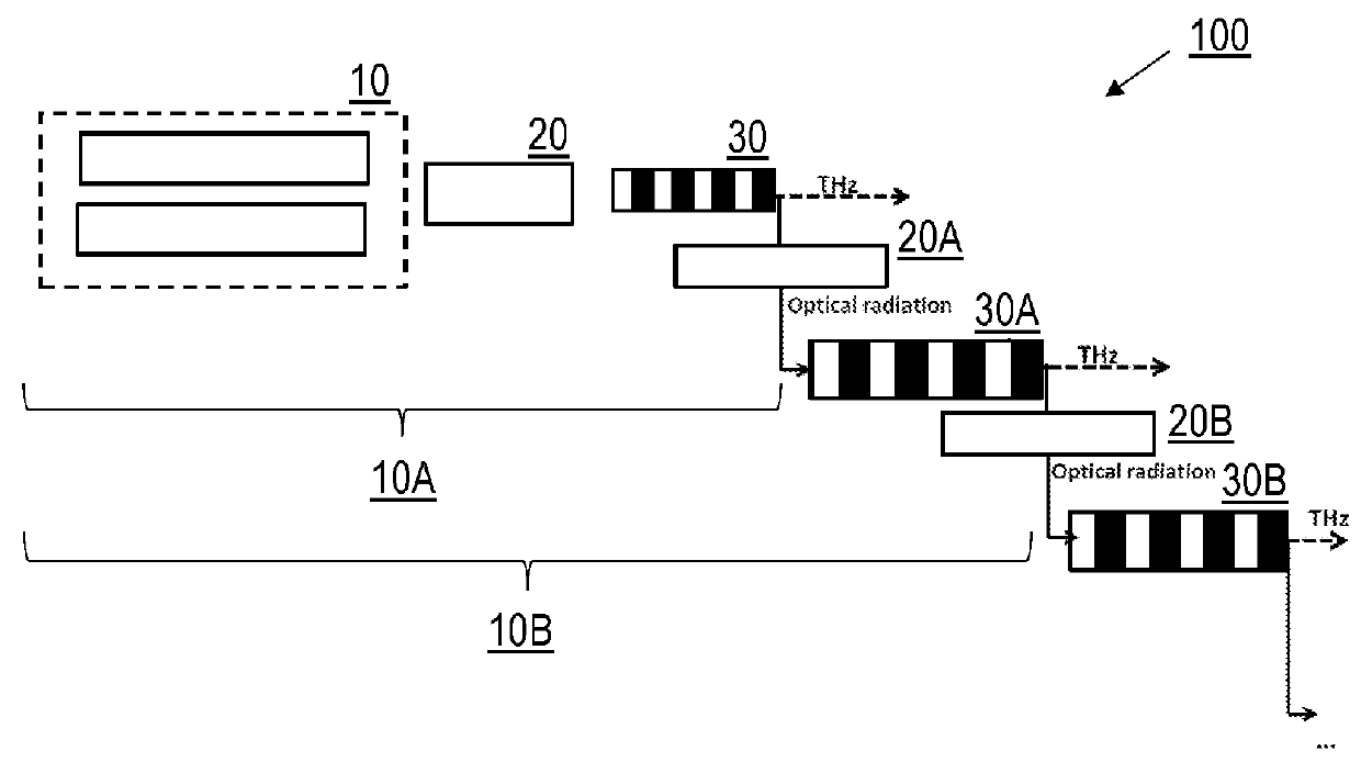
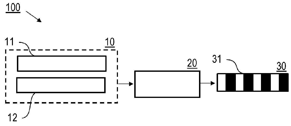
[0087]FIG. 1 shows a schematic of the THz source apparatus 100 comprising an input radiation source device 10 for generating optical input radiation, an imaging system 20 and a first conversion crystal device 30 for THz generation. The input radiation source device 10 comprises of a pump system with an optical pump source 11 creating a first radiation component and an optical seed source 12 creating a second radiation component. In this case, the THz source apparatus 100 is called Type O THz-COPA. In an alternative case (see FIG. 7), a THz seed source 13 is employed, and the THz source apparatus 100 is called Type T THz-COPA. Various possible implementations for the optical pump source 11 and optical seed source 12 are described below.

[0088]The imaging system 20 (details not shown) comprises refractive and / or reflective optics as well as a beam combiner unit, e.g., b...

second embodiment

of the Invention

[0114]Features of the second embodiment of the invention are described with reference to FIGS. 14 to 17.

[0115]FIG. 14 shows a schematic illustration of the THz source apparatus 100 comprising an input radiation source device 10 for generating multi-pulse optical input radiation, an imaging system 20 and a first conversion crystal device 30 for THz generation. The input radiation source device 10 is adapted for creating a sequence of ultrashort pulses having a temporal separation (Δt) equal to an integer multiple of a reciprocal of the THz frequency of the THz radiation to be generated (Δt=N·1 / fTHz, N=1, 2, . . . ). With this embodiment, the multi-line frequency spectrum is provided by the optical input radiation in the first conversion crystal device 30.

[0116]The temporal pulse format and corresponding spectrum of the optical input radiation in frequency domain is illustrated in FIG. 15. The temporal pulse format (FIG. 15B) is a sequence of ultrashort pulses in which...


PUM

PropertyMeasurementUnit
path lengthaaaaaaaaaa
powersaaaaaaaaaa

Abstract

A method of generating THz radiation includes the steps of generating optical input radiation with an input radiation source device (10), irradiating a first conversion crystal device (30) with the optical input radiation, wherein the first conversion crystal device (30) is arranged in a single pass configuration, and generating the THz radiation having a THz frequency in the first conversion crystal device (30) in response to the optical input radiation by an optical-to-THz-conversion process, wherein a multi-line frequency spectrum is provided by the optical input radiation in the first conversion crystal device (30), and the optical-to-THz-conversion process includes cascaded difference frequency generation using the multi-line frequency spectrum. Furthermore, a THz source apparatus being configured for generating THz radiation and applications thereof are described.

Description

CROSS-REFERENCE TO RELATED APPLICATIONS[0001]This application claims priority from EP 16 000 684.7 filed Mar. 21, 2016, which is incorporated herein by reference in its entirety.BACKGROUND OF THE INVENTION[0002]The invention relates to methods of generating THz (terahertz) radiation, in particular by irradiating a conversion crystal device with optical input radiation providing and generating the THz radiation by an optical-to-THz-conversion process. Furthermore, the invention relates to a THz source apparatus, being adapted for generating THz radiation and comprising an input radiation source device and a conversion crystal device for generating the THz radiation by the optical-to-THz-conversion process. Applications of the invention are available in driving strong field processes and especially acceleration of particles. According to a preferred application of the invention, the THz source apparatus is employed in a THz accelerator of charged particles, e.g., electrons.[0003]In th...

Claims


Application Information

Patent Timeline
Patent Type & Authority Applications(United States)
IPC IPC(8): G02F1/355G02F1/35
CPCG02F1/3534G02F1/39G02F2001/392G02F2201/16G02F2203/56G02F2001/3548G02F1/353G02F1/3558G02F1/3501G02F1/3544G02F2203/13G02F1/3551G02F1/392G02F1/3548
Inventor KAERTNER, FRANZ X.BARRE, DAMIAN N.HEMMER, MICHAELCIRMI, GIOVANNIMUECKE, OLIVER D.ROSSI, GIULIO MARIAFALLAHI, ARYAMATLIS, NICHOLAS H.ZAPATA, LUIS E.RAVI, KOUSTUBANREICHERT, FABIAN
Owner DEUTES ELEKTRONEN SYNCHROTRON DESY
Why Eureka
Try Eureka