Systems and methods for providing a dme l-band shared antenna

a technology of shared antennas and systems, applied in waveguide devices, instruments, reradiation, etc., can solve the problems of inability to produce practicable solutions, increase installation/wiring complexity, weight, cost,

Active Publication Date: 2017-09-21
AVIATION COMM AMP SURVEILLANCE SYST LLC
View PDF1 Cites 5 Cited by
  • Summary
  • Abstract
  • Description
  • Claims
  • Application Information

AI Technical Summary

Benefits of technology

[0007]Various embodiments include circuitry, that may comprise an interface to a bottom omni-directional antenna; a radio frequency splitter in switchable communication with the interface to the bottom omni-directional antenna; an interface between the radio frequency splitter and a distance measurement equipment receiver; and an interface between the radio frequency splitter and a surveillance receiver. This antenna may comprise an antenna of any type or capable of operating through any desired frequency range, in in one case, the omni-directional antenna of the present invention comprises an L-band antenna. Further, the circuitry of claim 1, wherein the circuity is configured to operate selectively in a surveillance transmit mode, a distance measurement equipment transmit mode, and a receive mode, and in additional implementations, the circuitry may further comprise a plurality of diodes configured to permit operation over a communication path based on the selected surveillance transmit mode, distance measurement equipment transmit mode, or receive mode. There are further embodiments provided that provide logic configured to prevent mutual transmission from a surveillance transmitt

Problems solved by technology

However, in prior implementations, separate antennae are required to support the various avionics frequencies and functions, and location on the aircraft for the required functionality can create additional installation/wiring complex

Method used


Image

  • Systems and methods for providing a dme l-band shared antenna
  • Systems and methods for providing a dme l-band shared antenna
  • Systems and methods for providing a dme l-band shared antenna

Examples


Embodiment Construction

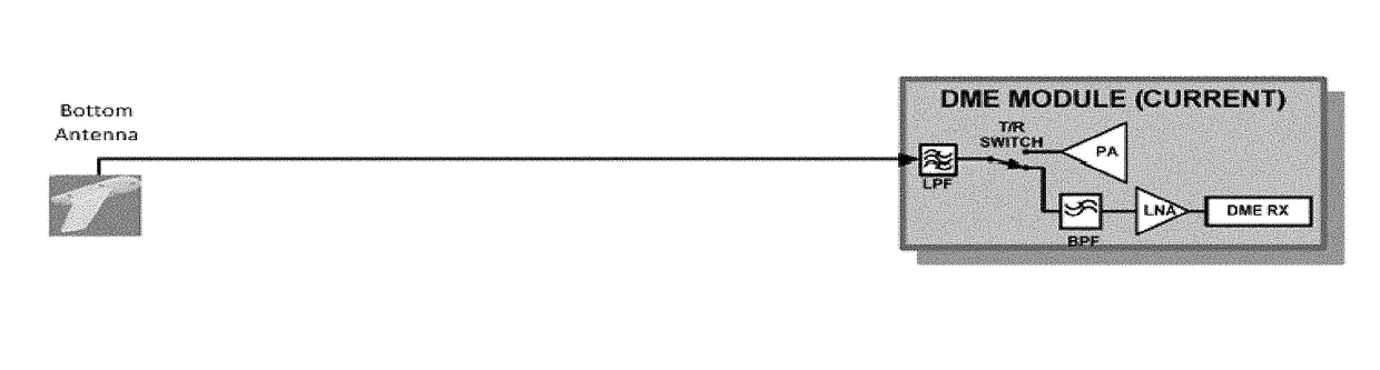
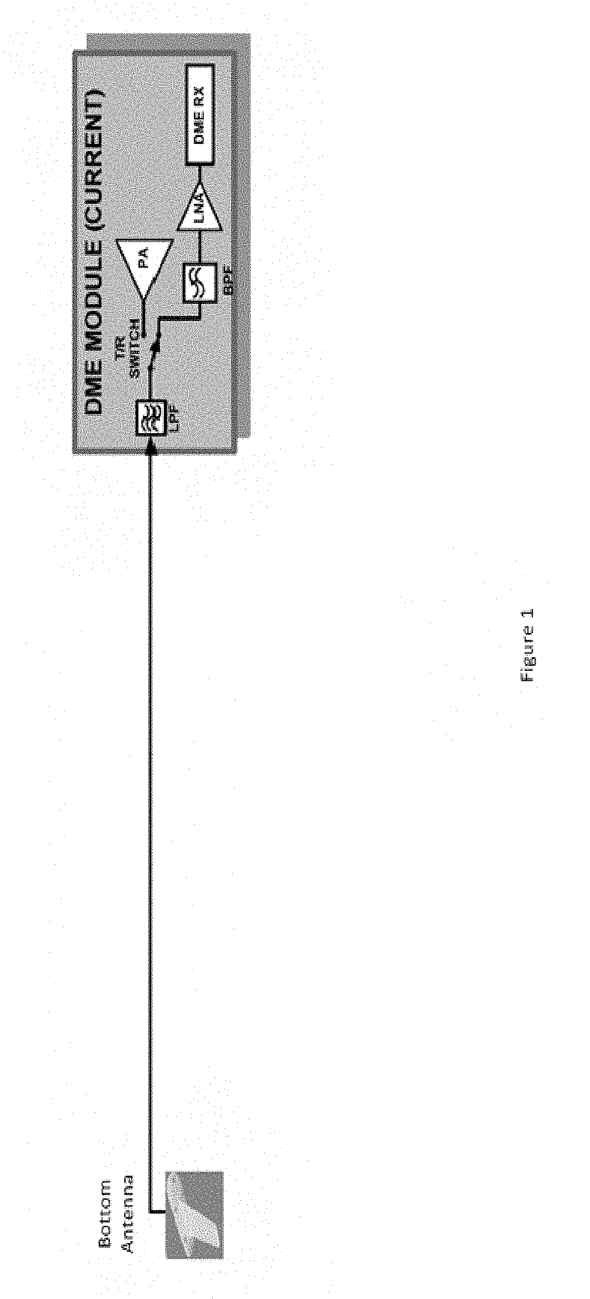
[0011]FIG. 1 illustrates a distance measurement equipment module and bottom antenna. As shown in FIG. 1, a current distance measurement equipment (DME) module can include a low pass filter (LPF) at an interface to a bottom antenna. The module can also include a power amplifier for a transmitter selectable connected to the low pass filter, using a transmit / receive (T / R) switch. In the receive position, the switch can further connect the low pass filter to a band pass filter (BPF). The band pass filter can provide a signal to a low noise amplifier (LNA). The amplifier can then provide the received signal to a distance measurement equipment receiver (RX).

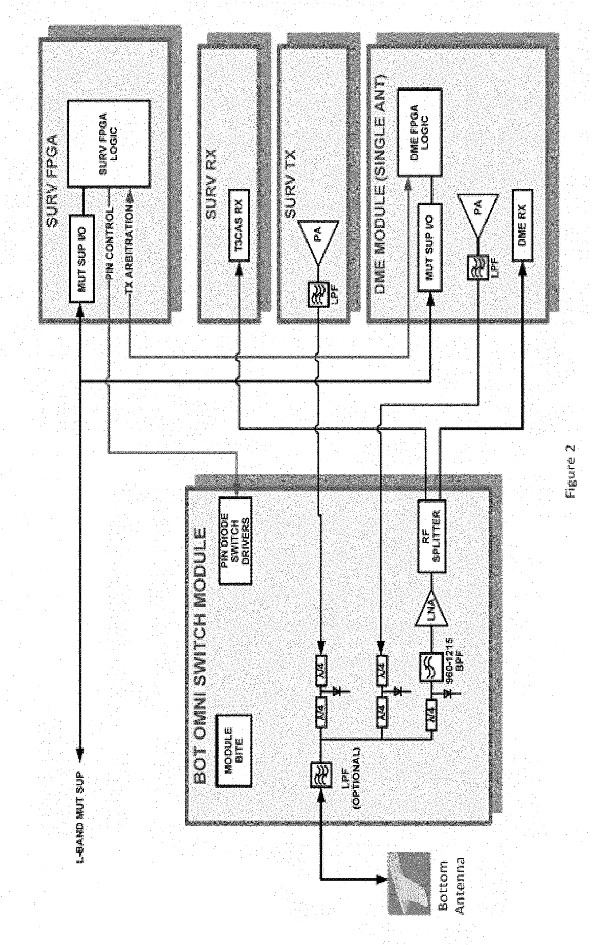
[0012]FIG. 2 illustrates a system according to certain embodiments of the present invention. For example, FIG. 2 provides a simplified block diagram showing an embodiment of the present invention for sharing a bottom omni-directional antenna between distance measuring equipment (DME) and surveillance (SURV) functions through the use of...


PUM


Abstract

Various wireless systems may benefit from suitable sharing of antennas and related equipment. For example a various avionics systems may benefit from systems and methods for providing a distance measurement equipment L-band shared antenna. Circuitry can include an interface to a bottom omni-directional antenna. The circuitry can also include a radio frequency splitter in switchable communication with the interface to the bottom omni-directional antenna. The circuitry can further include an interface between the radio frequency splitter and a distance measurement equipment receiver. The circuitry can additionally include an interface between the radio frequency splitter and a surveillance receiver.

Description

CROSS-REFERENCE TO RELATED APPLICATION[0001]This application is related to and claims the benefit and priority of U.S. Provisional Patent Application No. 62 / 310,245, filed Mar. 18, 2016, the entirety of which is hereby incorporated herein by reference.BACKGROUND[0002]Field[0003]Various wireless systems may benefit from suitable sharing of antennas and related equipment. For example a various avionics systems may benefit from systems and methods for providing a distance measurement equipment L-band shared antenna.[0004]Description of the Related Art[0005]Current L-Band avionics system functions, such as traffic alert and collision avoidance system (TCAS), Mode S transponders, air traffic control radar beacon system (ATCRBS) transponders, automatic dependent surveillance-broadcast (ADS-B) IN or OUT and distance measuring equipment (DME), provide stand-alone or integrated functional architectures where each single functional unit or integrated functional unit also contains the radio fr...

Claims


Application Information

Patent Timeline
IPC IPC(8): H01Q1/28H03F3/20H01P5/19H03F3/19H01Q5/50G01S13/93G01S13/933
CPCH01Q1/286H01Q5/50G01S13/9303H03F2200/451H03F3/19H03F3/20H01P5/19G01S5/0009G01S7/03G01S13/781G01S13/785G01S13/933G08G5/0004
Inventor TROXEL, JAMES R.
Owner AVIATION COMM AMP SURVEILLANCE SYST LLC
Why Eureka
Try Eureka