Engine-driven working machine

Active Publication Date: 2017-09-21
HONDA MOTOR CO LTD
View PDF3 Cites 4 Cited by
  • Summary
  • Abstract
  • Description
  • Claims
  • Application Information

AI Technical Summary

Benefits of technology

[0020]According to the present invention, the bottom portion of the fuel tank is inclined with a falling gradient toward the inverter from the intake port, and the

Problems solved by technology

However, when the first intake port that cools the inverter, and the second intake port that cools the fuel tank are respectively

Method used


Image

  • Engine-driven working machine
  • Engine-driven working machine
  • Engine-driven working machine

Examples


embodiment

[0029]The engine-driven working machine (more specifically, the generator) 10 according to the embodiment will be described.

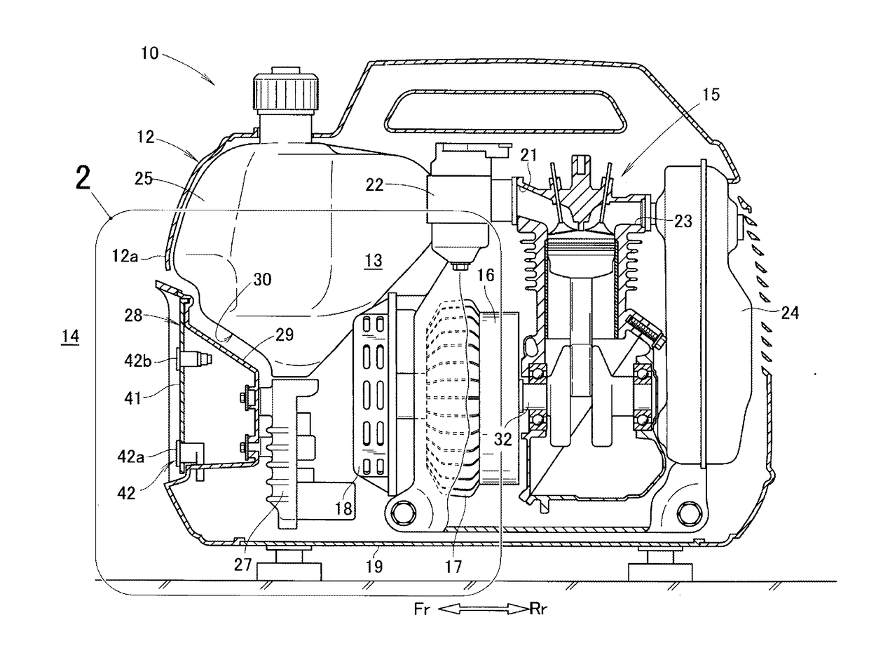
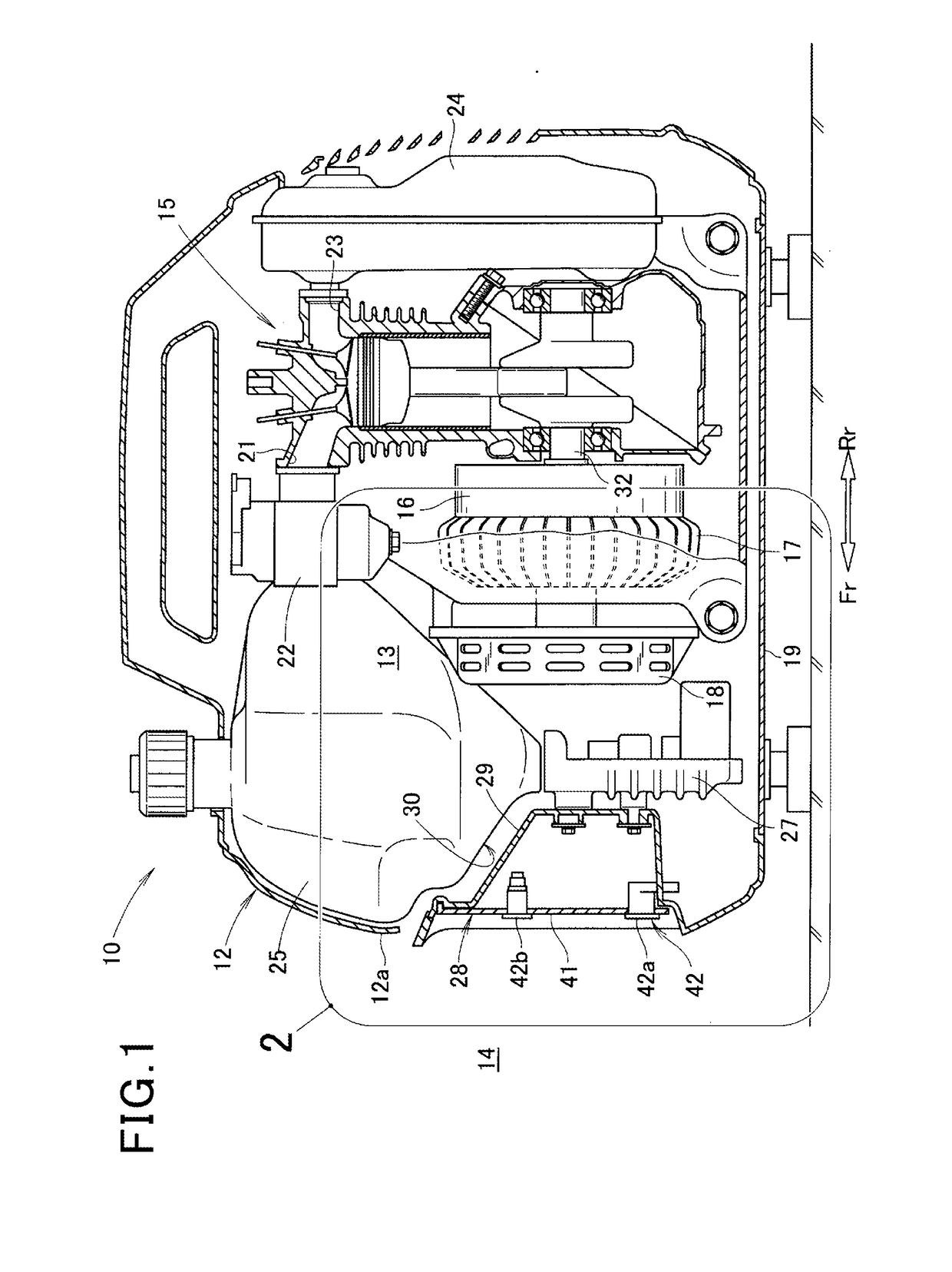
[0030]As illustrated in FIG. 1, the generator 10 includes an outer case 12 that forms an outer frame of the generator 10, an engine 15 that is housed in an inside 13 of the outer case 12, a power generating unit (a working unit) 16 that is provided at a front side of the engine 15, a cooling fan 17 that is provided at a front side of the power generating unit 16, and a recoil starter 18 that is provided at a front side of the cooling fan 17.

[0031]Further, the generator 10 includes a carburetor 22 that connects to an intake port 21 of the engine 15, a muffler 24 that connects to an exhaust port 23 of the engine 15, a fuel tank 25 that is disposed in front of the engine 15, an inverter 27 that is provided under the fuel tank 25, an operation section 28 that is provided on a case front wall 12a of the outer case 12, an operation cover (cover) 29 that covers equipm...


PUM


Abstract

An engine-driven working machine capable of reducing an opening of an outer case to be small, and decreasing the number of components is provided. An engine-driven working machine 10 is a generator in which an inverter 27 is provided at a suction side of a cooling fan 17, and a fuel tank 25 is provided over the inverter 27. The generator 10 includes an intake port 36 that is formed in an outer case 12, and a first air guide passage 61 that is formed by a tank bottom portion 38 of the fuel tank 25. The intake port 36 is formed in a lower side part 12b of a tank front wall 37, in the outer case 12. The first air guide passage 61 is formed by the tank bottom portion 38that is inclined with a falling gradient toward the inverter 27 from the intake port 36.

Description

INCORPORATION BY REFERENCE[0001]The present application claims priority under 35 U.S.C.§119 to Japanese Patent Application No. 2016-051635 filed on March 15, 2016. The content of the application is incorporated herein by reference in its entirety.BACKGROUND OF THE INVENTION[0002]Field of the Invention[0003]The present invention relates to an engine-driven working machine in which a cooling fan and an inverter are provided in an inside of an outer case.[0004]Description of the Related Art[0005]As an engine-driven working machine, there is known a generator in which a first intake port and a second intake port are formed in an outer case, an inverter is cooled with cooling air that is guided from the first intake port, and a fuel tank is cooled with cooling air that is guided from the second intake port (Refer to International Publication No. WO 2008 / 032414, for example.).[0006]However, when the first intake port that cools the inverter, and the second intake port that cools the fuel ...

Claims


Application Information

Patent Timeline
IPC IPC(8): H02K9/06H02K11/00H02K7/18F01P1/06F01P5/04
CPCH02K9/06F01P1/06H02K11/0094H02K7/1815F01P5/04F01P5/06F02B63/041F01P1/02F02B63/04F02B63/048F01P2001/005
Inventor KOYAMA, HIROSHIKAI, MASASHI
Owner HONDA MOTOR CO LTD
Why Eureka
Try Eureka