
Inductive charger alignment systems for vehicles

a technology of inductive charger and alignment system, which is applied in the direction of charging station, electric vehicle charging technology, transportation and packaging, etc., can solve the problems of battery drain in classic vehicles, significant problem of vehicle battery drain, and prolonged parking of classic vehicles

Active Publication Date: 2017-09-28
FORD GLOBAL TECH LLC
View PDF23 Cites 37 Cited by
  • Summary
  • Abstract
  • Description
  • Claims
  • Application Information

AI Technical Summary

Benefits of technology

The invention is about an inductive charging system for vehicles that can be charged in various environments without needing a fixed signal element. This makes the charging process more efficient and convenient, especially in places like open-air parking lots or attached garages within a home. The system includes an on-board signal element, which helps guide the vehicle into the proper alignment with the charger. Overall, this technology allows for seamless charging and flexibility in charging locations.

Problems solved by technology

Vehicle battery drain can be a significant problem for modern vehicles, particularly when the vehicles remained parked for long periods on the order of many months.
Classic vehicles, while generally not including as many electronic components and systems as modern vehicles, also can experience battery drain when parked for prolonged periods.
As classic vehicles are not frequently driven by their owners, battery drain remains a significant concern.
While such charging approaches are advantageous in requiring little, if any, physical actions by the driver of the vehicle to effect the charging compared to other conventional approaches (e.g., manipulation of trickle chargers, plug-in power cords, etc.), they often require much longer charging durations and exhibit low charging efficiency.
In an inductive charger system, for example, the alignment of the charging coils can drive charging efficiency, and conventional inductive charger systems often fail to account for alignment.
Further, conventional inductive charging systems that include some alignment capability generally convey alignment information to a driver with off-board displays, which can add significant cost to the system.

Method used


Image

  • Inductive charger alignment systems for vehicles
  • Inductive charger alignment systems for vehicles
  • Inductive charger alignment systems for vehicles

Examples


Embodiment Construction

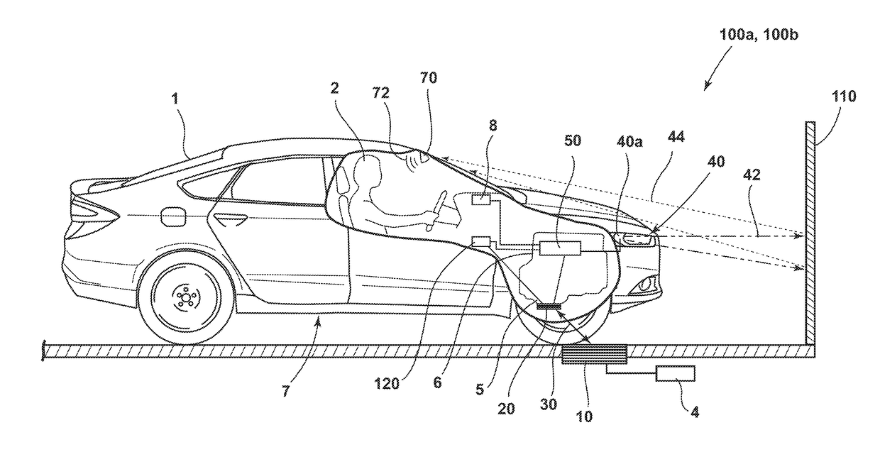
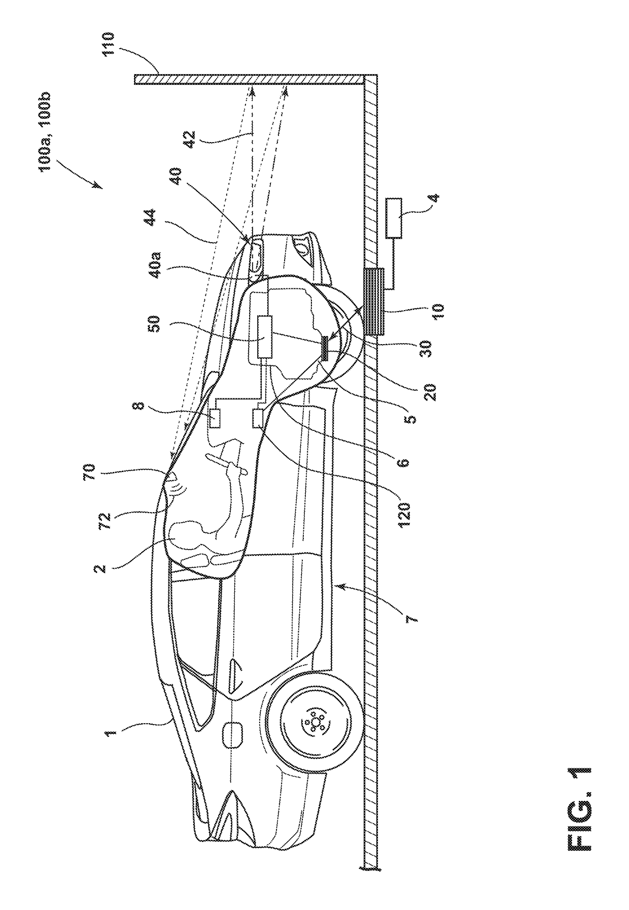
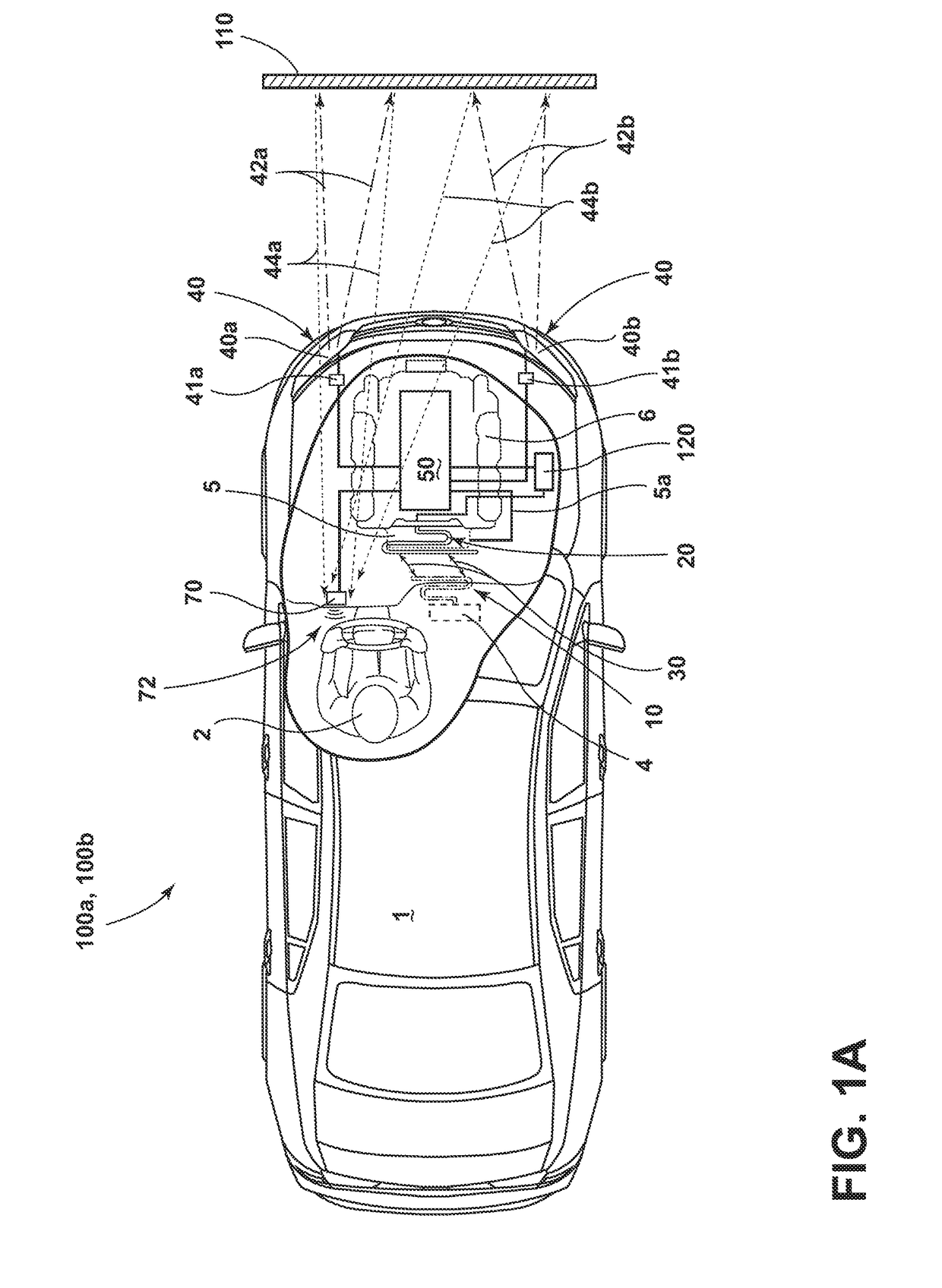
[0020]For purposes of description herein, the terms “upper,”“lower,”“right,”“left,”“rear,”“front,”“vertical,”“horizontal,”“interior,”“exterior,”“vehicle forward,”“vehicle rearward,”“vehicle side-to-side” and derivatives thereof shall relate to the invention as oriented in FIGS. 1, 1A and 2A. However, the invention may assume various alternative orientations, except where expressly specified to the contrary. Also, the specific devices and assemblies illustrated in the attached drawings and described in the following specification are simply exemplary embodiments of the inventive concepts defined in the appended claims. Hence, specific dimensions and other physical characteristics relating to the embodiments disclosed herein are not to be considered as limiting, unless the claims expressly state otherwise.

[0021]Described in this disclosure are inductive charger alignment systems for vehicles and, in more particular embodiments, inductive charger alignment systems for vehicles that emp...


PUM


Abstract

An inductive charger alignment system for a vehicle that includes: a plurality of on-board inductive receiving coils adapted to charge an on-board power source; an alignment controller coupled to the coils; an on-board signal element, e.g., a pair of headlamps, coupled to the controller; and an off-board inductive transmitter coil. Further, the controller is configured to direct the element to communicate an alignment between the receiving coils and the transmitter coil to an on-board driver. The alignment may include vehicle forward and side-to-side alignment between the receiving coils and the off-board transmitter coil.

Description

FIELD OF THE INVENTION[0001]The present invention generally relates to inductive charger alignment systems for vehicles and, in more particular embodiments, to inductive charger alignment systems for vehicles that employ an on-board signal element to communicate alignment information to the driver of the vehicle.BACKGROUND OF THE INVENTION[0002]Modern vehicles include various electronic components and systems that require significant power usage while parked. For example, many modern vehicles employ alarm systems with associated sensors and alarms that require power while parked. Other modern vehicles include status reporting systems and other electronic components that drain power while parked. Vehicle battery drain can be a significant problem for modern vehicles, particularly when the vehicles remained parked for long periods on the order of many months. Classic vehicles, while generally not including as many electronic components and systems as modern vehicles, also can experien...

Claims


Application Information

Patent Timeline
Patent Type & Authority Applications(United States)
IPC IPC(8): B60L11/18
CPCB60L11/1829B60L11/182B60L11/1835B60L53/12B60L53/38Y02T90/16Y02T90/14H02J50/10H02J50/90B60L53/36B60L53/37B60L53/60B60L53/124B60L53/126Y02T10/7072Y02T90/12Y02T10/70
Inventor SALTER, STUART C.DANOWSKI, CHRISTOPHER A.DELLOCK, PAUL KENNETHBUTTOLO, PIETRO
Owner FORD GLOBAL TECH LLC
Learn More