Control apparatus for internal combustion engine

a control apparatus and internal combustion engine technology, applied in mechanical apparatus, electric control, machines/engines, etc., can solve problems such as condensed water, adverse effects at locations, and exhaust channels

Inactive Publication Date: 2017-09-28
TOYOTA JIDOSHA KK
View PDF7 Cites 6 Cited by
  • Summary
  • Abstract
  • Description
  • Claims
  • Application Information

AI Technical Summary

Benefits of technology

[0031]Therefore, the control apparatus of the present disclosure can reduce concern that, as a result of the condensed water flowing into the intake channel through the EGR valve after the EGR valve normal drive is started under a condition in which the condensed water remains in the exhaust-channel-side portion, the condensed water may generate an adverse e

Problems solved by technology

Therefore, in the internal combustion engine disclosed in JP 2007-198310A, there is a concern that the condensed water that has been blown off to the exhaust channel from the EGR channel in the duration in which the EGR valve is closed may generate an adverse effect at locations, such as the exhaust channel.
Further, in the internal combustion engine disclosed in JP 2007-198310A, there is a concern that, since the condensed water in the EGR channel is not evaporated

Method used


Image

  • Control apparatus for internal combustion engine
  • Control apparatus for internal combustion engine
  • Control apparatus for internal combustion engine

Examples


Embodiment Construction

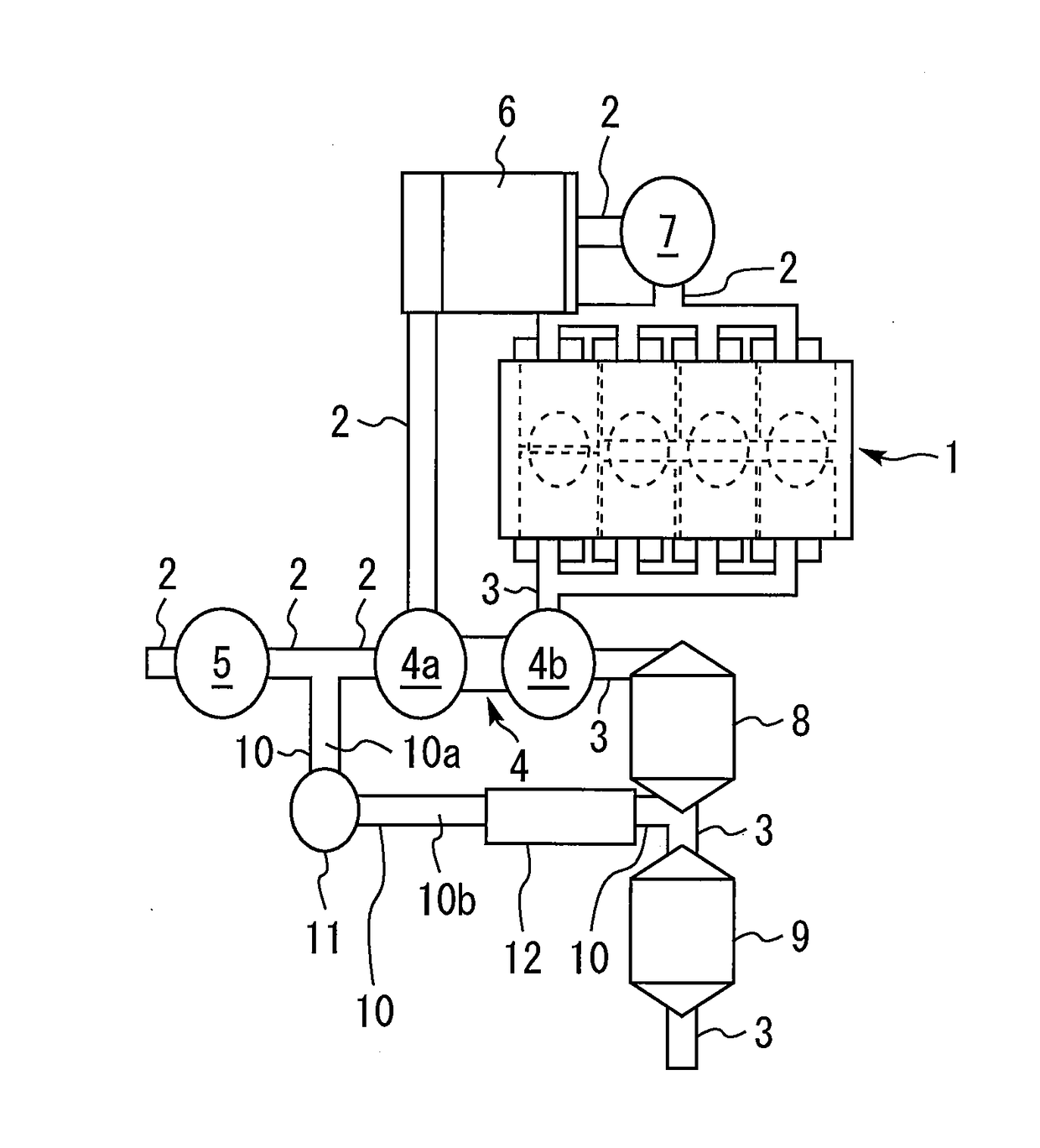
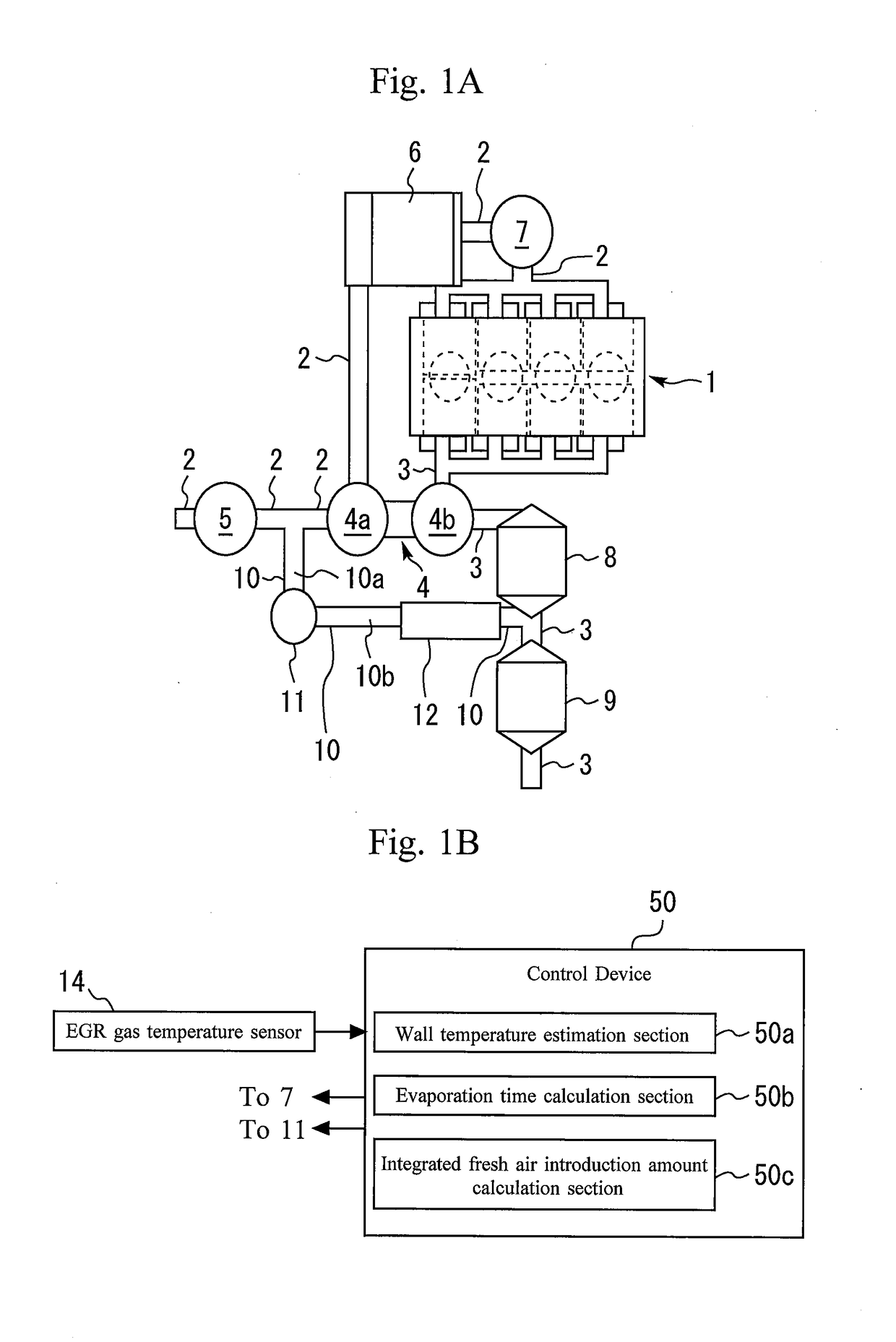
[0038]In the following, a first embodiment according to a control apparatus for an internal combustion engine of the present disclosure will be described. FIGS. 1A and 1B are schematic views that illustrate an example of an engine system to which the control apparatus for the internal combustion engine according to the first embodiment is applied.

[0039]In the example shown in FIG. 1A, an intake channel 2 and an exhaust channel 3 are connected to an internal combustion engine main body 1. In the intake channel 2, a compressor 4a of a supercharging device 4 is installed. In the exhaust channel 3, a turbine 4b of the supercharging device 4 is installed. That is, in the example shown in FIG. 1A, intake air pressurized by the compressor 4a of the supercharging device 4 is supplied to the internal combustion engine main body 1.

[0040]Also, in the example shown in FIG. 1A, an air cleaner 5 is installed at a portion of the intake channel 2 on the upstream side of the compressor 4a. An interc...


PUM


Abstract

A control apparatus for an internal combustion engine that includes an EGR channel and an EGR valve is configured, when the internal combustion engine is in a warm-up process and when an intake air flow rate that is a flow rate of air supplied to the internal combustion engine main body is less than or equal to a predetermined value, to open the EGR valve with a minute opening degree that is an opening degree smaller than a minimum opening degree of the EGR valve with which a condensed water in an exhaust-channel-side portion that is a portion of the EGR channel on a side closer to the exhaust channel relative to the EGR valve flows into an intake-channel-side portion that is a portion of the EGR channel on a side closer to the intake channel relative to the EGR valve.

Description

CROSS-REFERENCE TO RELATED APPLICATION[0001]This application is based on and claims the benefit of Japanese Patent Application No. 2016-057173, filed on Mar. 22, 2016, which is incorporated by reference herein in its entirety.BACKGROUND[0002]Technical Field[0003]The present disclosure relates to a control apparatus for an internal combustion engine that includes an EGR channel and an EGR valve.[0004]Background Art[0005]An internal combustion engine that includes an EGR channel and an EGR valve is known. JP 2007-198310A discloses an example of this kind of internal combustion engine. The internal combustion engine disclosed in JP 2007-198310A is provided with: a supercharging device that supplies a pressurized intake air to an internal combustion engine main body; an EGR channel that recirculates, into an intake channel connected to the internal combustion engine main body, a part of exhaust gas that flows in an exhaust channel connected to the internal combustion engine main body; a...

Claims


Application Information

Patent Timeline
IPC IPC(8): F02D41/00F02M26/36
CPCF02M26/36F02D41/0077F02D2041/1472F02D41/047F02D2041/0067F02D2041/007Y02T10/40
Inventor HAGA, HIROYUKI
Owner TOYOTA JIDOSHA KK
Why Eureka
Try Eureka