Fast density estimation method for defect inspection application

a density estimation and defect technology, applied in the field of image processing, can solve the problems of blob density estimation being slowed down, high speed inspection suffering from low density estimation, etc., and achieve the effect of fast density estimation

Active Publication Date: 2017-09-28
HONG KONG APPLIED SCI & TECH RES INST
View PDF15 Cites 3 Cited by
  • Summary
  • Abstract
  • Description
  • Claims
  • Application Information

AI Technical Summary

Benefits of technology

[0007]Accordingly, the presently claimed invention provid

Problems solved by technology

Along these lines, the blob density estimation will be slowed down and the

Method used


Image

  • Fast density estimation method for defect inspection application
  • Fast density estimation method for defect inspection application
  • Fast density estimation method for defect inspection application

Examples


Embodiment Construction

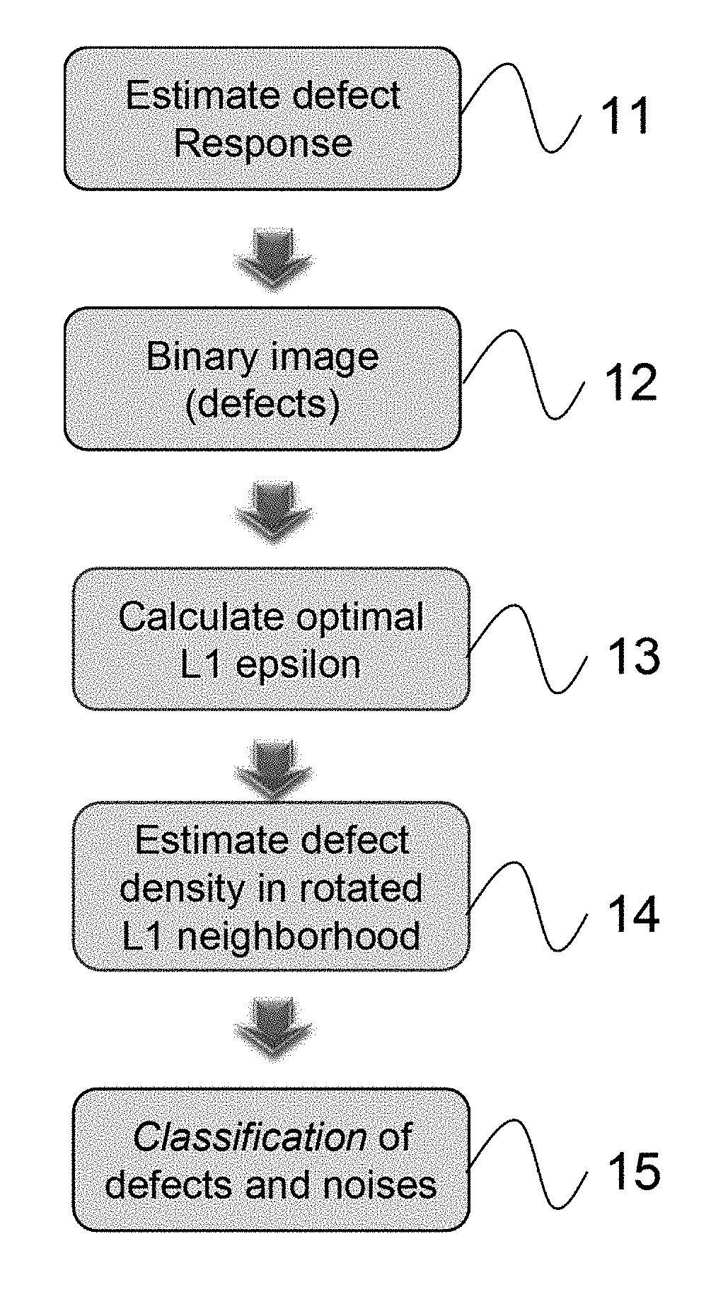
[0039]In the following description, a method for inspecting one or more defects of an object by using defect density estimation is set forth as preferred examples. It will be apparent to those skilled in the art that modifications, including additions and / or substitutions may be made without departing from the scope and spirit of the invention. Specific details may be omitted so as not to obscure the invention; however, the disclosure is written to enable one skilled in the art to practice the teachings herein without undue experimentation.

[0040]In the light of the foregoing background, it is an object of the present invention to provide a spatial density estimation algorithm to estimate defect density map for defect inspection.

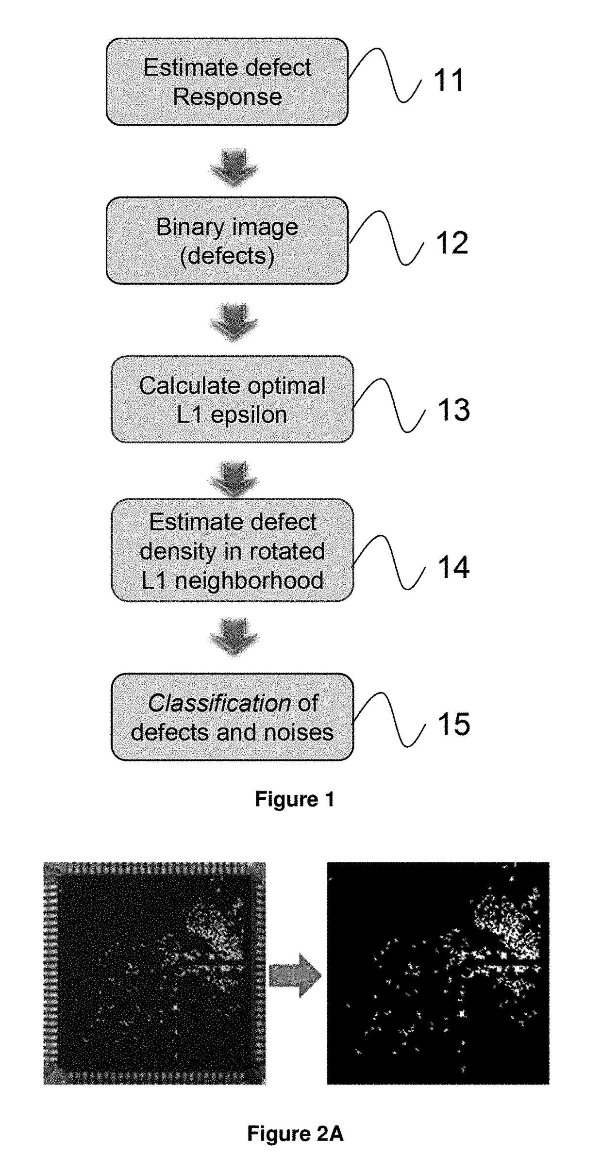
[0041]FIG. 1 is a flowchart of a density estimation method for defect inspection, according to one embodiment. As shown in FIG. 1, the step 11 is to capture one or more images for defect estimation on a surface of an object. In one embodiment, images are sequ...


PUM


Abstract

The present invention provide a high speed spatial density estimation algorithm to estimate defect density maps for blob analysis in an image processing field for inspection. The method of the present invention uses a rotated L1 epsilon-ball neighborhood mask for determining a defect density for each of target pixels to generate a defect density map for defect detection of an object. The present method is capable of providing high detection speed and substantially eliminating influence of the noise from images.

Description

COPYRIGHT NOTICE[0001]A portion of the disclosure of this patent document contains material, which is subject to copyright protection. The copyright owner has no objection to the facsimile reproduction by anyone of the patent document or the patent disclosure, as it appears in the Patent and Trademark Office patent file or records, but otherwise reserves all copyright rights whatsoever.FIELD OF THE INVENTION[0002]This invention relates to the field of image processing and, more particularly, to image analysis for defect inspection.BACKGROUND[0003]Defect inspection in manufacturing is conducting inspection during the production process. This approach of inspection helps control the quality of products by fixing the sources of defects immediately after they are detected, and it is useful for any factory that wants to improve productivity, reduce defect rates, and reduce re-work and waste. The measurement of defect information is usually conducted on component texture information or he...

Claims


Application Information

Patent Timeline
IPC IPC(8): G06T7/00G06T5/30G06T5/00G06K9/66
CPCG06T7/0008G06K9/66G06T5/30G06K9/00G06T2207/20036G06T2207/20081G06K9/62G06T5/002G06T7/0004G06F18/00
Inventor ZOU, WEIWEN
Owner HONG KONG APPLIED SCI & TECH RES INST
Why Eureka
Try Eureka