Power converter

a power converter and converter technology, applied in the direction of electric variable regulation, process and machine control, instruments, etc., can solve the problems of lowering reliability and difficulty in performing and achieve the effect of improving the reliability of the maximum power point tracking control

Active Publication Date: 2017-09-28
HITACHI INFORMATION & TELECOMM ENG LTD
View PDF2 Cites 17 Cited by
  • Summary
  • Abstract
  • Description
  • Claims
  • Application Information

AI Technical Summary

Benefits of technology

[0010]According to the invention, the plurality of converters include the maximum power point tracking units and the plurality of converters are controlled by the result that is obtained by unifying the results of the maximum...

Problems solved by technology

In the power converter disclosed in JP-A-2011-141794, since one power converter performs the maximum power point tracking control, in a case where a trouble su...

Method used


Image

  • Power converter
  • Power converter
  • Power converter

Examples


embodiment 1

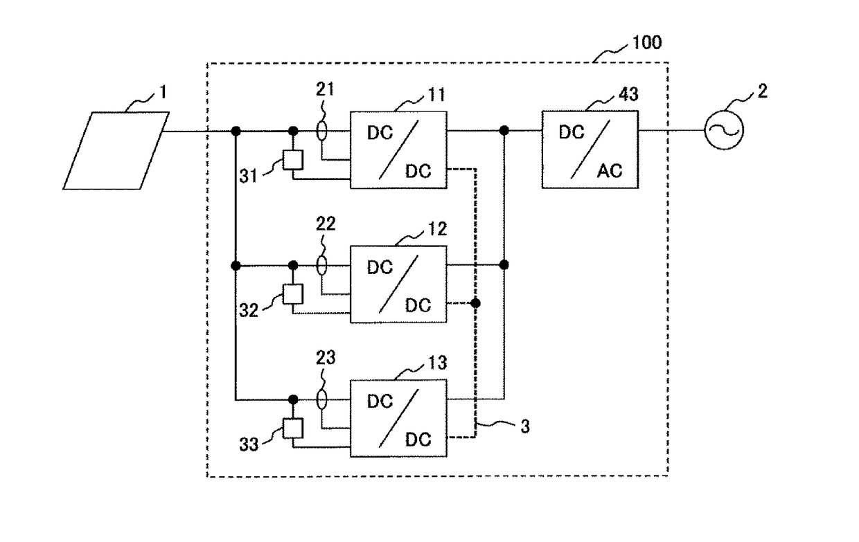
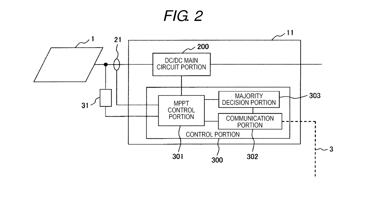
[0021]FIG. 1 is a schematic configuration diagram of a power converter of Embodiment 1 of the invention.

[0022]As illustrated in FIG. 1, a DC power is input into a power converter 100 from a solar cell 1 and the power converter 100 outputs an AC power to an AC system 2. The power converter 100 includes DC-DC converters 11 to 13 which are connected in parallel, an inverter 43 which is connected to ends thereof, current sensors 21 to 23 which respectively detect input currents of the DC-DC converters 11 to 13, voltage sensors 31 to 33 which detect input voltages, a communication line 3 for communicating between the DC-DC converters 11 to 13.

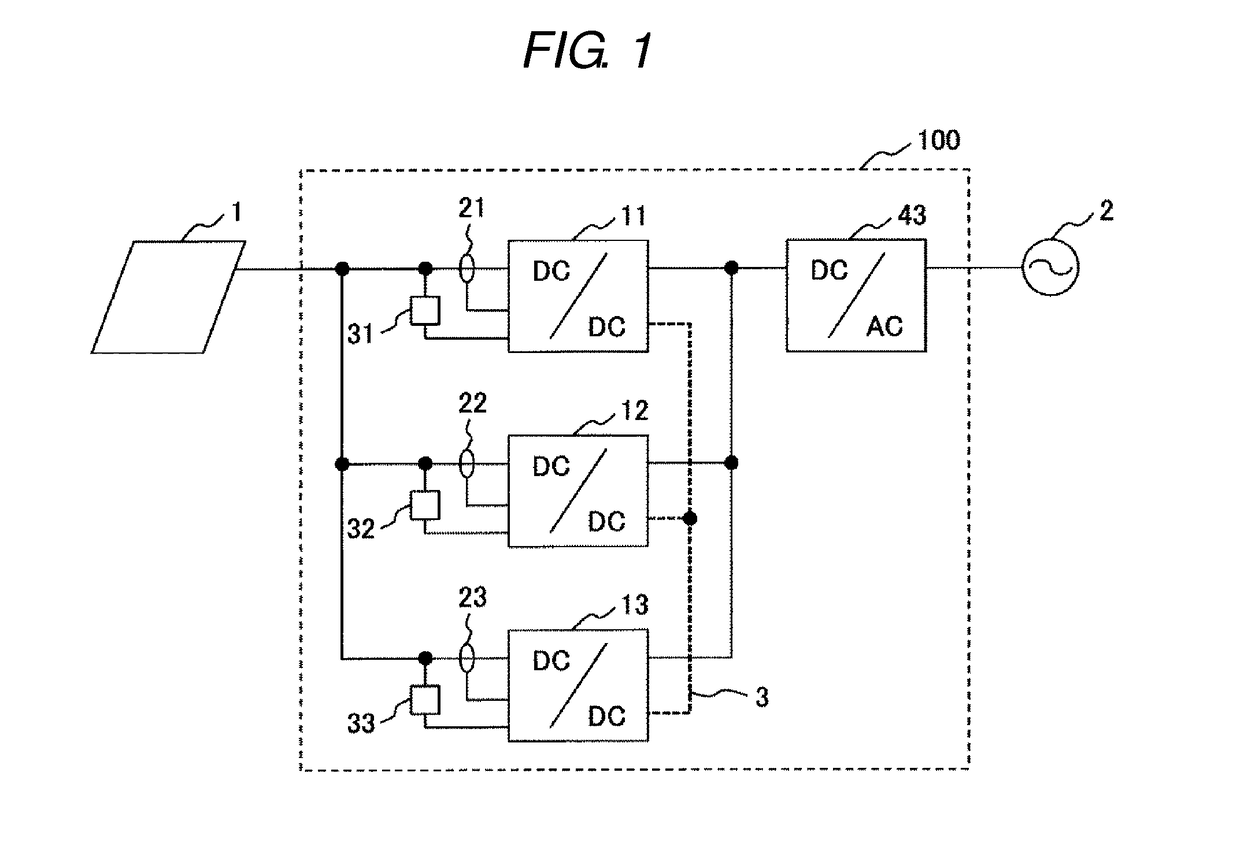
[0023]The DC-DC converters 11 to 13 include the maximum power point tracking (hereinafter, referred to as MPPT) control units that control a voltage and a current that are an operating point of the solar cell 1 so as to take out a maximum power from the solar cell 1. The DC-DC converters 11 to 13 supply the DC power to the inverter 43. In addition, ...

embodiment 2

[0058]FIG. 5 is a schematic configuration diagram of a power converter of Embodiment 2 of the invention.

[0059]As illustrated in FIG. 5, a DC power is input into a power converter 101 from a solar cell 1 and the power converter 101 outputs an AC power to an AC system 2. The power converter 101 includes converters 64 to 66 which are connected in parallel and a communication line 4 for communicating between the converters 64 to 66. The converters 64 to 66 respectively include DC-DC converters 14 to 16, inverters (DC-AC converters) 44 to 46 which are connected rear stages thereof, current sensors 24 to 26 which detect an input current of each of the converters 64 to 66, voltage sensors 34 to 36 which detect the input voltages, and control portions 54 to 56.

[0060]The control portions 54 to 56 of the converters 64 to 66 include MPPT control portions for taking out a maximum power from the solar cell 1. The MPPT calculation is performed to maximize the input power of each of the converters...


PUM


Abstract

A power converter includes a plurality of converters which are connected in parallel to a DC power supply in which an operating point is changed in accordance with an output current or an output voltage. The plurality of converters include maximum power point tracking units for performing maximum power point tracking calculations of the DC power supply. Results of the maximum power point tracking calculations of the plurality of converters are unified between the plurality of converters and the plurality of converters are controlled based on the unified calculation result.

Description

[0001]The present application claims priority from Japanese application serial no. 2016-61660, filed on Mar. 25, 2016, the content of which is hereby incorporated by reference into this application.BACKGROUND OF THE INVENTION[0002]Field of the Invention[0003]The present invention relates to a power converter in which a plurality of converters are connected in parallel.[0004]Description of Prior Art[0005]In recent years, from growing awareness of global environmental conservation, a system including a distributed power supply such as a solar cell and a fuel cell has been developed. In general, a power converter that is used for a solar power generation system includes a maximum power point tracking (MPPT) control device that maximizes power input from the solar cell.[0006]As related art, a power converter in which a plurality of power converters are connected in parallel to configure further large power converter is disclosed in JP-A-2011-141794. In the power converter, one power con...

Claims


Application Information

Patent Timeline
IPC IPC(8): H02J3/38H02M7/537H02M3/158
CPCH02J3/385H02J3/387H02M7/537H02M3/158H02M3/1582H02M3/1584H02J2300/30H02J2300/26H02J3/381Y02E10/56H02J3/46H02M7/515
Inventor SHIMADA, TAKAETAKAHASHI, FUMIKAZUTANIGUCHI, KIMIAKIABE, KOSUKE
Owner HITACHI INFORMATION & TELECOMM ENG LTD
Why Eureka
Try Eureka