LED lighting system with battery for demand management and emergency lighting

a technology of demand management and battery backup, applied in the field of led lighting, can solve the problems of battery failure, inconvenient system for providing battery backup to an led, and inability to meet the needs of emergency lighting, so as to reduce current draw and improve the life of energy storage devices.

Active Publication Date: 2017-09-28
LEDVANCE LLC +1
View PDF2 Cites 34 Cited by
  • Summary
  • Abstract
  • Description
  • Claims
  • Application Information

AI Technical Summary

Benefits of technology

[0006]FIG. 2 illustrates a circuit arrangement that represents the current state-of-the-art. A battery backup system 200 is arranged between an AC mains 202 and a set of one or more LEDs 204. Via a latching single or multi-pole relay 203 (or other means), the battery backup system 200 can be connected to or disconnected from the AC mains 202 and the one or more LEDs 204. The relay 203 also disconnects the battery backup system 200 from the one or more LEDs 204 during normal operation of the AC mains 205 so that the LEDs 204 are powered without interference. When a power outage occurs, or some other issue occurs with the AC mains 202, the backup system 200 is engaged. This means that it is disconnected from the AC mains 202, and at the same time the relay 203 connects a voltage to current converter 216 to the one or more LED lights 204 via the relay 203. The LED driver 218 then ceases to provide power to the one or more LEDs 204. Thus, the one or more LEDs 204 are prevented from simultaneously being driven by both the LED driver 218 and the battery backup system 200. Preferably, the AC mains 202 comes back online before the voltage across the battery 208 runs too low, and the LED driver 218 can resume providing power to the one or more LEDs 204 and the backup system 200 can replenish the charge on the battery 208.
[0020]In some embodiments, the first control circuit includes a non-transitory tangible computer readable medium comprising instructions for charging and discharging the energy storage device so as to improve a lifetime of the energy storage device while also reducing a current draw of the second current source when electricity pricing is above a threshold or above a running average.

Problems solved by technology

This system for providing battery backup to an LED is necessarily expensive owing to the separate control systems: one for the LED driver 218 and one for the battery backup system 200.
Unfortunately, because the lights may be located in an inaccessible location such as a ceiling, they often go neglected.
Thus battery failure occurs, the warning light is ignored (or the system goes untested), and the emergency lighting system does not produce light when needed.

Method used


Image

  • LED lighting system with battery for demand management and emergency lighting
  • LED lighting system with battery for demand management and emergency lighting
  • LED lighting system with battery for demand management and emergency lighting

Examples


Embodiment Construction

[0064]The word “exemplary” is used herein to mean “serving as an example, instance, or illustration.” Any embodiment described herein as “exemplary” is not necessarily to be construed as preferred or advantageous over other embodiments.

[0065]For purposes of this disclosure, a “backup battery” is any battery or other storage device that can be electrically coupled to an LED driver and provide backup LED driving power in the event of a loss of primary power (e.g., AC mains power). Other terms for a backup battery include a ballast or emergency ballast.

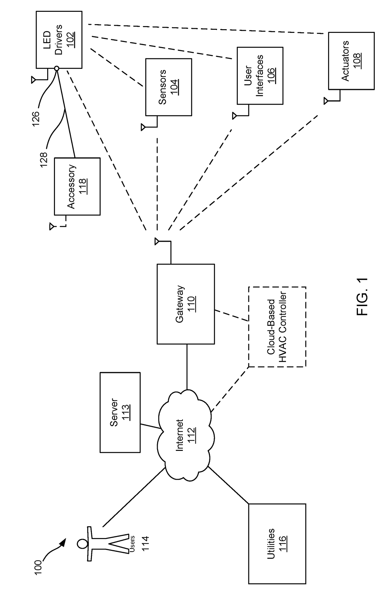
[0066]For the purposes of this disclosure, a “bus” is any physical arrangement of data and / or power transmission components (e.g., electrical and / or optical) that transfer data to each component on the bus. Each device has a unique ID, and devices only pay attention to those signals that are addressed to them. As used herein, a bus carries both power and data, and powers at least some of the devices coupled to the bus. For instance, cont...


PUM


Abstract

This disclosure describes systems, methods, and apparatus for a combined LED driver and emergency backup battery system. The LED driver can include current regulation circuitry as well as a bus enabling charging and discharging of an energy storage device from and to the bus. A master controller can control charging and discharging of the energy storage device via a controller of an energy storage management system, and also communicate with the current regulation circuitry to control a balance of power between an AC mains, the energy storage device, and driving of an LED light source. Accessories may be coupled to the bus and receive low voltage power from the bus and optionally receive commands from the master controller and provide sensed data back to the controller. A wireless network interface to the master controller can enable system states based on electrical power company indications and instructions.

Description

CLAIM OF PRIORITY UNDER 35 U.S.C. §119[0001]The present application for patent claims priority to Provisional Application No. 62 / 305,442 entitled “LED LIGHTING SYSTEM WITH BATTERY FOR DEMAND MANAGEMENT AND EMERGENCY LIGHTING” filed Mar. 8, 2016, and assigned to the assignee hereof and hereby expressly incorporated by reference herein.FIELD OF THE DISCLOSURE[0002]The present disclosure relates generally to LED lighting. In particular, but not by way of limitation, the present disclosure relates to systems, methods and apparatuses for LED lighting having a backup battery.DESCRIPTION OF RELATED TECHNOLOGIES[0003]While the majority of light for commercial spaces are powered from mains power, it is a requirement to provide a certain portion of the lighting with battery backup. The battery serves as an alternate power supply in the event the mains supply of electrical utility power is interrupted. This allows sufficient lighting so the occupied space will allow the safe egress of people. ...

Claims


Application Information

Patent Timeline
Patent Type & Authority Applications(United States)
IPC IPC(8): H02J9/06H05B37/02H02J7/00H05B33/08H02J7/04H05B44/00
CPCH02J9/061H05B33/0815H05B37/0272H05B33/0851H02J7/0068H02J7/04H05B45/10H05B47/19H02J7/007Y02B20/30H05B45/3725
Inventor CATALANO, ANTHONY W.DAVIS, STEVEN S.TEPLIN, CHARLESMCDOUGLE, ANTHONY N.
Owner LEDVANCE LLC
Why Eureka
Try Eureka