Reservoir tank mounting structure of saddle riding vehicle

a technology for riding vehicles and tanks, applied in the direction of reserve arrangements, cycle equipments, cycle brakes, etc., can solve the problems of forced maintenance and increase the stiffness of the rear fender frame, and achieve the effect of increasing the number of parts and increasing the stiffness

Active Publication Date: 2017-10-05
HONDA MOTOR CO LTD
View PDF0 Cites 1 Cited by
  • Summary
  • Abstract
  • Description
  • Claims
  • Application Information

AI Technical Summary

Benefits of technology

[0008]An aspect of the present invention is directed to provide a reservoir tank mounting structure of a saddle riding vehicle capable of preventing deposits from being collected on an outer surface of a reservoir tank while suppressing an increase in the number of parts.
[0024]According to the aspect of the present invention, since the tank supporting section is installed at the auxiliary machine case and the outer surface covering wall is formed at the tank supporting section substantially conforming to the outer surface shape of the reservoir tank, a gap of the outer surface side of the reservoir tank can be decreased using the auxiliary machine case. Accordingly, according to the aspect of the present invention, deposits can be prevented from being collected on the outer surface of the reservoir tank while suppressing an increase in the number of parts. In addition, according to the aspect of the present invention, the outer surface of the reservoir tank can be protected using the auxiliary machine case.

Problems solved by technology

For this reason, deposits such as dust, mud, or the like, are likely to be collected on the upper surface of the reservoir tank upon use of the vehicle, and frequent maintenance is forced.

Method used


Image

  • Reservoir tank mounting structure of saddle riding vehicle
  • Reservoir tank mounting structure of saddle riding vehicle
  • Reservoir tank mounting structure of saddle riding vehicle

Examples


Embodiment Construction

[0033]Hereinafter, an embodiment of the present invention will be described based on the accompanying drawings. Further, directions of forward, rearward, left, right, and so on, described below are the same as directions of a vehicle described below unless the context clearly indicates otherwise.

[0034]In addition, in appropriate places in the drawings used in the following description, an arrow FR showing a forward direction with respect to a vehicle, an arrow LH showing a leftward direction with respect to the vehicle and an arrow UP showing an upward direction with respect to the vehicle are provided.

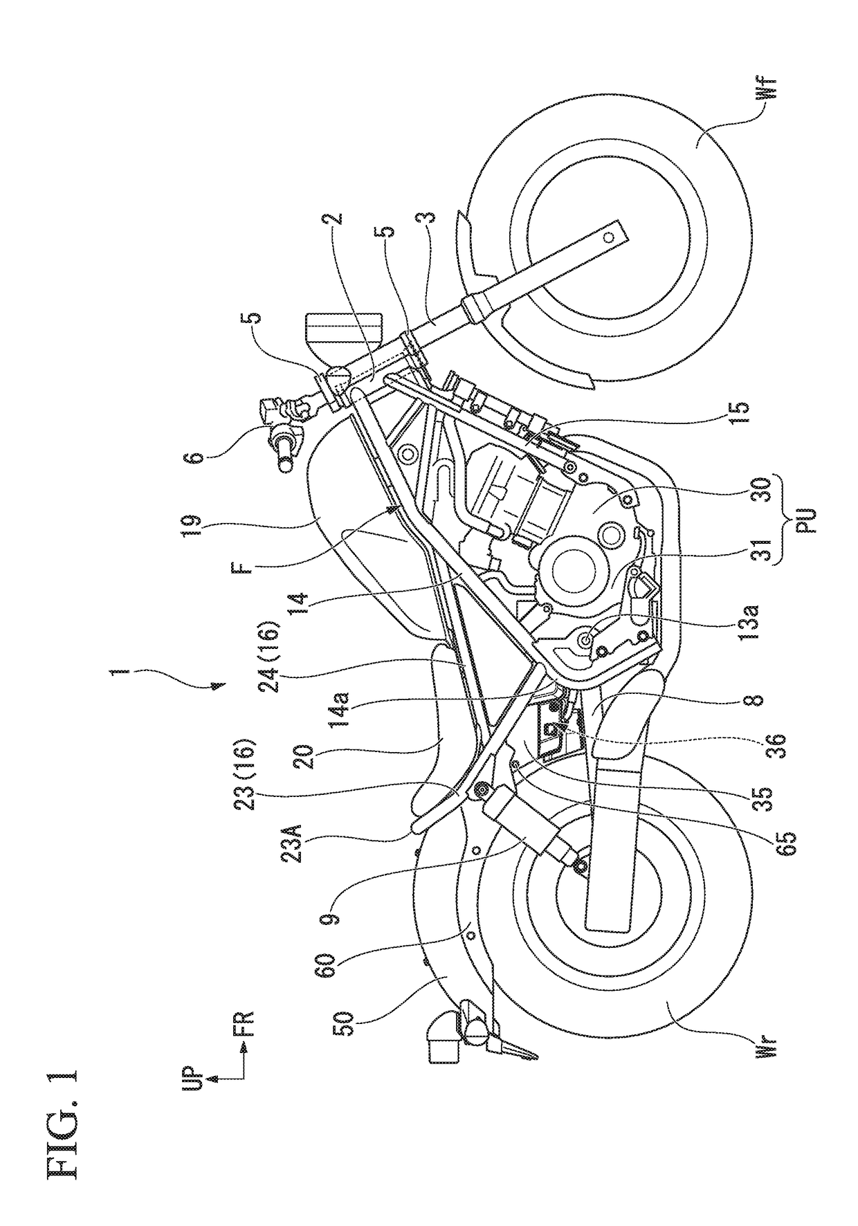
[0035]FIG. 1 is a view showing a right side surface of a saddle riding vehicle according to an embodiment. The saddle riding vehicle according to the embodiment is a so-called cruiser type motorcycle 1 in which a vehicle height is decreased and a forward / rearward length is increased. A front wheel Wf of the motorcycle 1 is rotatably supported by lower end portions of a pair of left an...


PUM


Abstract

A reservoir tank mounting section includes a reservoir tank configured to store a hydraulic fluid of a brake apparatus, and an auxiliary machine case. The auxiliary machine case has a tank supporting section configured to hold the reservoir tank. The tank supporting section is constituted by a recessed section in which an outer surface of the auxiliary machine case is recessed inward. The tank supporting section is formed substantially along an outer surface shape of the reservoir tank and has an outer surface covering wall configured to cover an outer surface of the reservoir tank.

Description

CROSS-REFERENCE TO RELATED APPLICATION[0001]Priority is claimed on Japanese Patent Application No. 2016-073074, filed Mar. 31, 2016, the content of which is incorporated herein by reference.BACKGROUNDField of the Invention[0002]The present invention relates to a reservoir tank mounting structure of a saddle riding vehicle such as a motorcycle or the like.Description of Related Art[0003]In a saddle riding vehicle such as a motorcycle or the like, a reservoir tank configured to store a hydraulic fluid of a brake apparatus is mounted, and for example, a decrement of a hydraulic fluid in a master cylinder is replenished with the hydraulic fluid in the reservoir tank.[0004]It is preferable that the reservoir tank does not bulge outward in a vehicle width direction when it is mounted on the vehicle, and disposition relations or the like of the other in-vehicle parts are devised variously (for example, Japanese Unexamined Patent Application, First Publication No. 2008-94161).[0005]In a res...

Claims


Application Information

Patent Timeline
Patent Type & Authority Applications(United States)
IPC IPC(8): B60T17/06B62J99/00
CPCB62J99/00B60T17/06B62L3/023B62J15/00
Inventor KOISHIKAWA, TAKUMASAKAI, TORUHIRAMARU, MASAYUKI
Owner HONDA MOTOR CO LTD
Why Eureka
Try Eureka