Computational imaging with uncalibrated pupil phase

Active Publication Date: 2017-10-05
RAYTHEON CO
View PDF0 Cites 4 Cited by
  • Summary
  • Abstract
  • Description
  • Claims
  • Application Information

AI Technical Summary

Benefits of technology

The patent describes methods and systems for improving the resolution of imaging systems that use a detector array to capture images. The system uses an uncalibrated variable phase plate to introduce a controllable blur to the image, which is then recovered using digital signal processing to recover sub-pixel information from the blurred image. The optical system may also under-sample the image to reduce the sampling parameter, but the system uses the uncalibrated variable phase plate to increase the effective sampling parameter. The recovered image is then processed using an image restoration algorithm to produce an unblurred image with higher effective sampling parameter. The technical effects of this patent include improved performance and resolution of focal plane sampling limited imaging systems.

Problems solved by technology

That is, the optical system image quality is at best diffraction limited, having a sampling parameter Q that is less than or equal to the Nyquist value of 1, such that aliasing is a concern.

Method used


Image

  • Computational imaging with uncalibrated pupil phase
  • Computational imaging with uncalibrated pupil phase
  • Computational imaging with uncalibrated pupil phase

Examples


Embodiment Construction

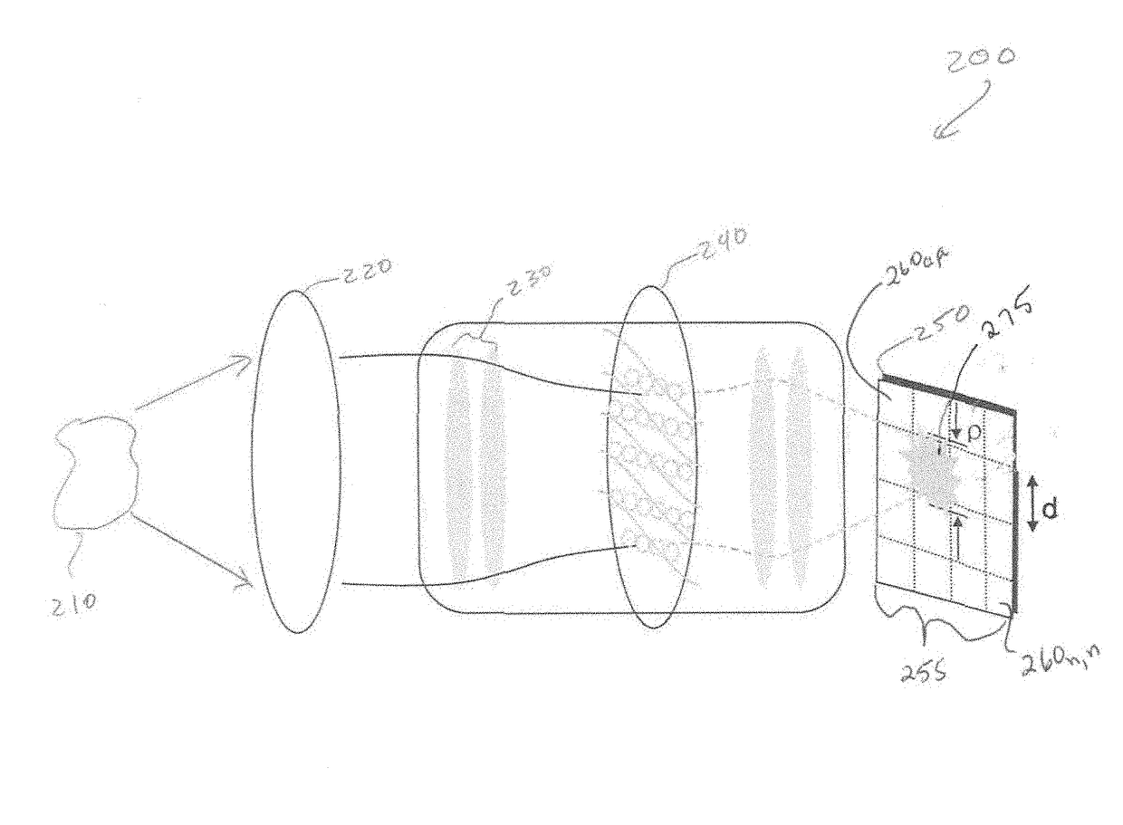
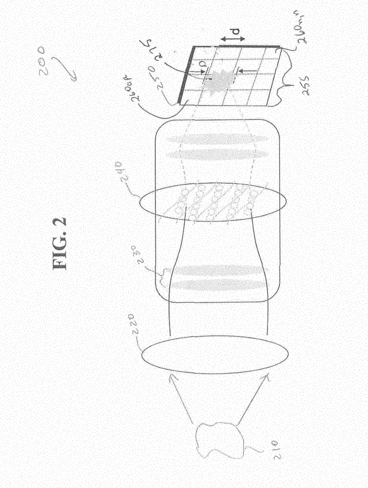
[0016]In the description that follows, like components have been given the same reference numerals, regardless of whether they are shown in different examples. To illustrate an example(s) of the present disclosure in a clear and concise manner, the drawings may not necessarily be to scale and certain features may be shown in somewhat schematic form. Features that are described and / or illustrated with respect to one example may be used in the same way or in a similar way in one or more other examples and / or in combination with or instead of the features of the other examples.

[0017]As the term is used herein “atmospheric distortion” includes optical distortion arising from the turbulent air motion that drives variations in index of refraction. These optical distortions can be modeled and predicted using theories such as that developed by A. N. Kolmogorov, V. I. Tatarskii, and D. L. Fried (Roggermann and Welsh, Imaging through Turbulence, CRC Press, Boca Raton, Fla., 2006, the contents...


PUM


Abstract

Systems and methods are disclosed for improving image quality by modifying received radiation wavefronts with one or more uncalibrated variable phase plates at the pupil plane of the optical system, to produce an atmospheric-like blurred image on the focal plane with an effective increase in the sampling parameter Q. Real-time image restoration algorithms may then be applied to data sets sampled from the blurred image formed on the detector array. Numerous phase plate embodiments are provided for modifying the wavefront.

Description

U.S. GOVERNMENT INTEREST[0001]There is no U.S. Government ownership or other interest in the invention(s) described and claimed herein.FIELD[0002]This invention relates to computational imaging using a combination of an un-calibrated phase plate and post processing, and in particular methods and systems for computationally efficient improvement of the focal plane image sampling parameter Q, also referred to as super-resolution.BACKGROUND[0003]Imaging system design using focal plane detector arrays is becoming ubiquitous, and the image formation burden is increasingly shared between the optical train and digital processing of the raw detector array data. Imaging system resolution, focal plane array sampling, and field of view are a function of the imaging sampling parameter Q, where Q=λ*(focal ratio) / (detector element size). The degree of spreading (blurring) of the image of a point source is a measure for the quality of an imaging system. Current practice is frequently to settle for...

Claims


Application Information

Patent Timeline
IPC IPC(8): G06T5/00G06T3/40
CPCG06T3/4069G06T5/003G02B26/06G06T5/73G01J9/00
Inventor CROWE, DEVON G.KNOERNSCHILD, CALEB
Owner RAYTHEON CO
Why Eureka
Try Eureka