Electronic apparatus with pocket of low permittivity material to reduce electromagnetic interference

Active Publication Date: 2017-10-05
DENSO CORP
View PDF0 Cites 0 Cited by
  • Summary
  • Abstract
  • Description
  • Claims
  • Application Information

AI Technical Summary

Benefits of technology

The present patent text describes an electronic apparatus having a first substrate with a first surface and a second surface, a first switch, an insulation layer, and a second substrate with a pocket of low permittivity. The technical effect of the invention is that it enables high-frequency switching between the first and second switches by creating a connection on the first surface of the first substrate. Additionally, it provides improved insulation between the first and second switches using the insulation layer, which reduces interference and improves the overall performance of the electronic apparatus.

Problems solved by technology

The power modules such as the charger, converter, and inverter generate an electrical noise.
The electric noise caused by parasitic capacitance in the power module is one of the major sources of noise.
In particular, a parasitic capacitance associated with chips of the power modules may be a source of electrical noise.
The electrical noise further propagates through the power module to other components.
The electric noise generated by the chips may propagate through the power module, and may interfere with other electronic devices of the vehicle.
For example, the charger, the inverter, and the converter generate noise which may propagate and may interfere with other vehicle components, such as auxiliary electronics and / or an electric motor.
Typically, the noise filters can be bulky and heavy, thereby increasing the weight and footprint of the power module.
The noise filters may occupy a significant portion of the footprint of the power modules.

Method used


Image

  • Electronic apparatus with pocket of low permittivity material to reduce electromagnetic interference
  • Electronic apparatus with pocket of low permittivity material to reduce electromagnetic interference
  • Electronic apparatus with pocket of low permittivity material to reduce electromagnetic interference

Examples


Embodiment Construction

[0019]The description set forth below in connection with the appended drawings is intended as a description of various embodiments of the disclosed subject matter and is not necessarily intended to represent the only embodiment(s). In certain instances, the description includes specific details for the purpose of providing an understanding of the disclosed embodiment(s). However, it will be apparent to those skilled in the art that the disclosed embodiment(s) may be practiced without those specific details. In some instances, well-known structures and components may be shown in block diagram form in order to avoid obscuring the concepts of the disclosed subject matter.

[0020]Reference throughout the specification to “one embodiment” or “an embodiment” means that a particular feature, structure, or characteristic described in connection with an embodiment is included in at least one embodiment of the subject matter disclosed. Thus, the appearance of the phrases “in one embodiment” or ...


PUM


Abstract

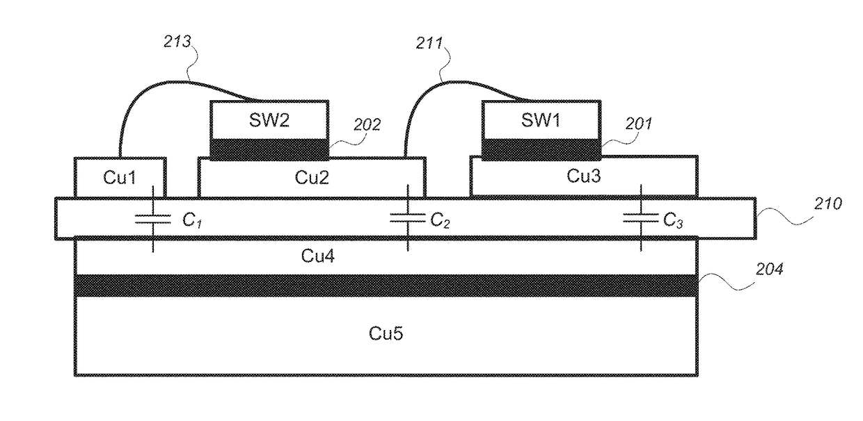
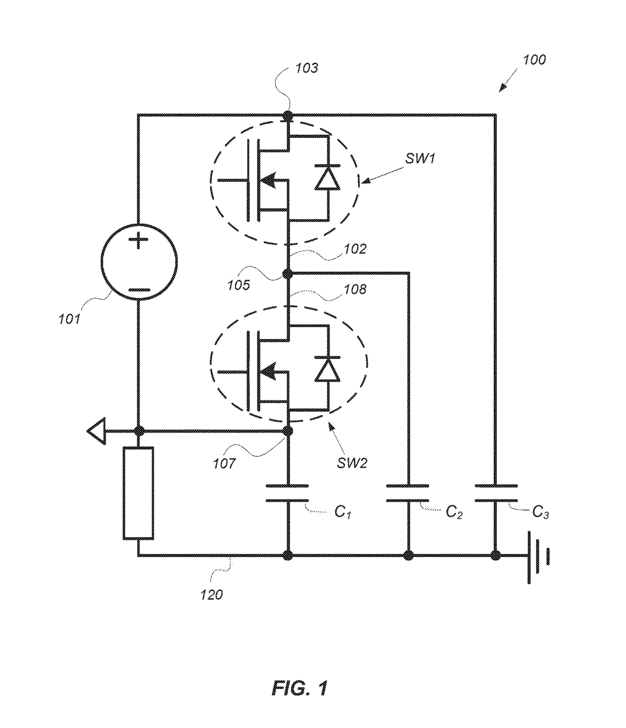
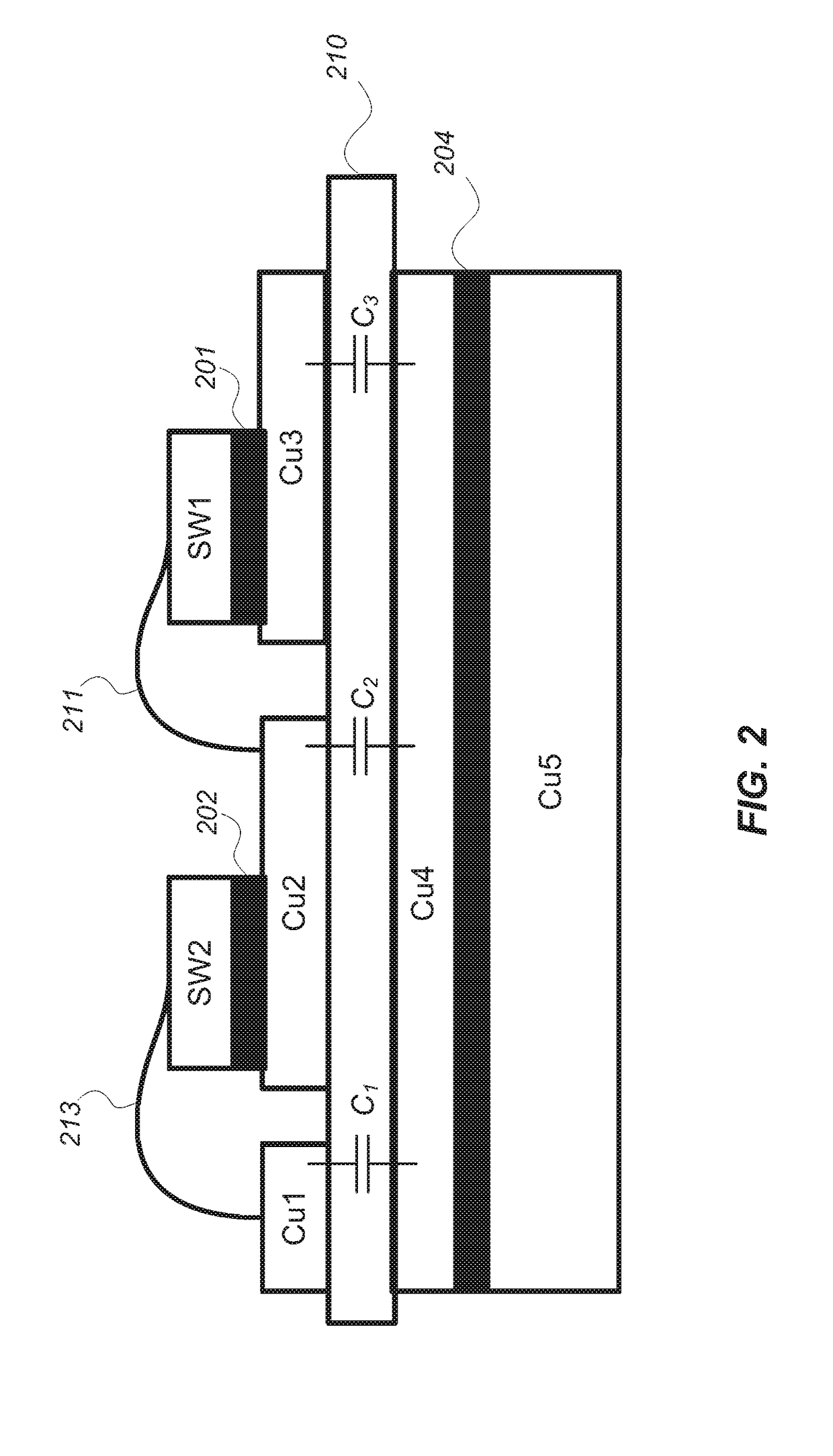
An electronics apparatus including a first substrate having a first surface and a second surface, a first switch connected to a second switch and soldered in series on the first surface of the first substrate creating a connection to allow switching between the first switch and the second switch at high frequency, an insulation having a third surface attached to the second surface of the first substrate, and a second substrate having a pocket of low permittivity located between the first switch and the second switch on a fourth surface of the insulation, the fourth surface being opposite to the third surface where the first switch and the second switch are located.

Description

BACKGROUND[0001]Field of the Disclosure[0002]This application relates generally to improvements in power electronics module. More particularly the present disclosure relates a direct bond copper modified to reduce the electromagnetic interference and noise.[0003]Description of the Related Art[0004]Power modules of power electronics may be utilized in electric vehicles (EV) and hybrid electric vehicles (HEV) as a charger (changing AC to DC), an inverter (changing DC to AC), and / or a converter (DC to DC).[0005]The power modules such as the charger, converter, and inverter generate an electrical noise. The electric noise caused by parasitic capacitance in the power module is one of the major sources of noise. In particular, a parasitic capacitance associated with chips of the power modules may be a source of electrical noise. The electrical noise further propagates through the power module to other components.[0006]The electric noise generated by the chips may propagate through the pow...

Claims


Application Information

Patent Timeline
IPC IPC(8): H01L23/495H01L23/00H01L25/07
CPCH01L23/49589H01L27/0711H01L23/49562H01L23/49575H01L23/49582H01L23/49568H01L24/48H01L24/32H01L24/73H01L2924/17747H01L2224/48091H01L2224/48106H01L2224/48225H01L2224/32245H01L2224/73265H01L2924/30105H01L2924/19041H01L2924/19102H01L2924/05032H01L2924/05432H01L2924/1715H01L27/0727H01L21/8228H01L25/072H01L23/3735H01L23/642H01L24/29H01L2224/32225H01L2224/48227H01L2224/83447H01L2224/83801H01L2224/85447H01L2924/00014H01L2224/29101H01L2924/014H01L2224/45099H01L2924/00012
Inventor SHIN, JONGWONWANG, CHI-MING
Owner DENSO CORP
Why Eureka
Try Eureka