Electrical leakage detection circuit and electrical leakage breaker
- Summary
- Abstract
- Description
- Claims
- Application Information
AI Technical Summary
Problems solved by technology
Method used
Image
Examples
first embodiment
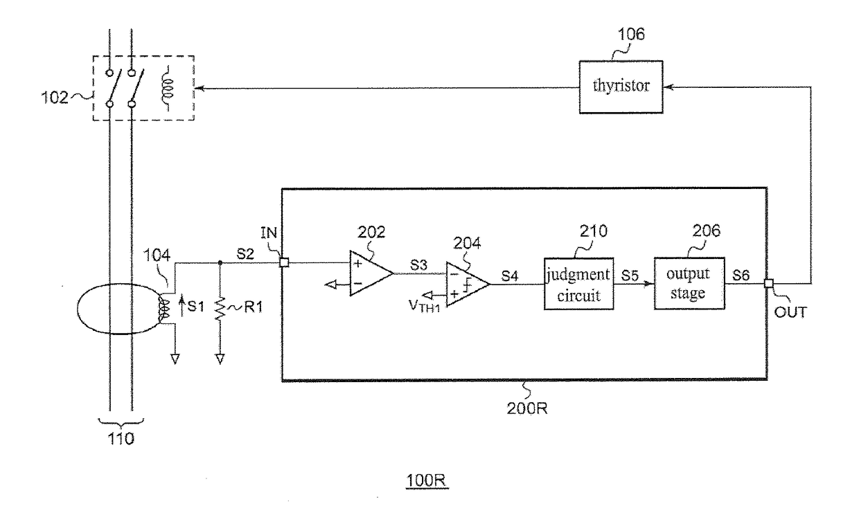
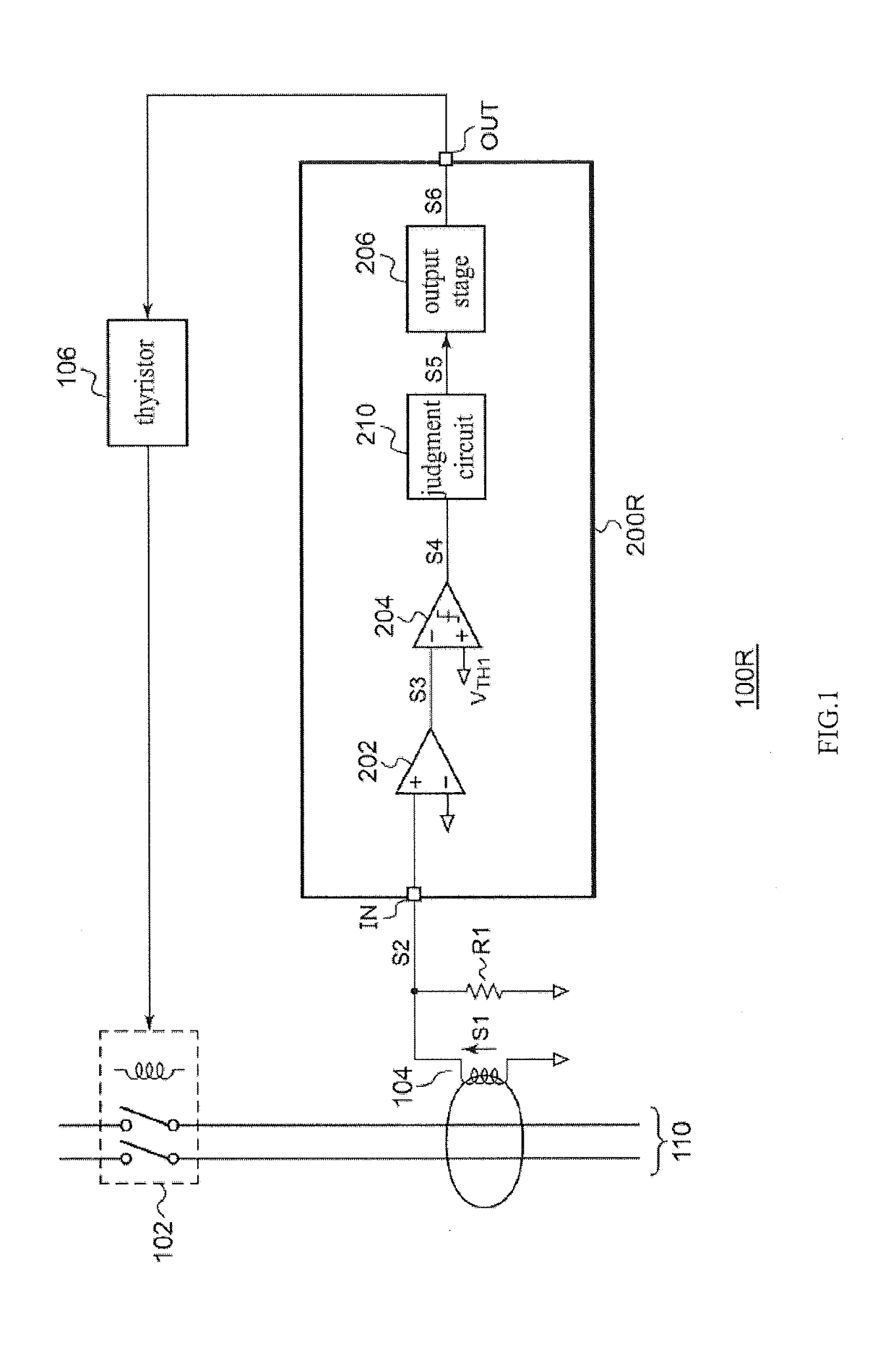
[0059]FIG. 5 is a circuit diagram of an electrical leakage detection circuit 200a according to a first embodiment. A judgment circuit 220a includes a first timer circuit 221 and a waveform judging portion 222. The first timer circuit 221 asserts a first temporary judgment signal S9 when a first comparison signal S4 remains continuously at a predetermined level (that is, a level suggesting the possibility of electrical leakage) for a predetermined length of time. In this embodiment, the first temporary judgment signal S9 is also used as the mask signal S7 and is supplied to the waveform judging portion 222 and a mask circuit 230.
[0060]In one example, the first timer circuit 221 is configured with an analog timer. When the first comparison signal S4 is asserted, a switch 226 is turned off and a switch 223 is turned on, and a capacitor C1 is charged by a current generated by a current source 224. A comparator 225 asserts the first temporary judgment signal S9 when a voltage VC1 of the ...
second embodiment
[0064]FIG. 6 is a circuit diagram of an electrical leakage detection circuit 200b according to a second embodiment. The judgment circuit 220a of FIG. 6 is similar to that of FIG. 5. In addition to the judgment signal S5 and the mask signal S7, a feedback signal S10 generated in an output stage 250 and indicating a state of a latch circuit 252 is input in the mask circuit 230b. The feedback signal S10 is asserted (for example, set to high level) when the latch circuit 252 is activated and negated (for example, set to low level) when the latch circuit 252 is inactive.
[0065]The mask circuit 230b includes an OR circuit 234 for generating a logical sum S11 of the mask signal S7 and the feedback signal S10, and an AND circuit 236 for generating a logical multiply of the logical sum S11 and the judgment signal S5. The mask circuit 230b generates a latch input signal S8 according to the output of the AND circuit 236.
[0066]According to this mask circuit 230b, assertion of the judgment signal...
third embodiment
[0076]FIG. 8 is a circuit diagram of an electrical leakage detection circuit 200c according to a third embodiment. The electrical leakage detection circuit 200c includes a second comparator COMP2 in addition to the electrical leakage detection circuit 200b of FIG. 6. The second comparator COMP2 generates a second comparison signal S12 indicating a comparison result between a detected signal S3 from a zero-phase-sequence current transformer 104 and a predetermined second threshold voltage VTH2. For example, the second threshold voltage VTH2 is negative, and the second comparator COMP2 asserts the second comparison signal S12 when S3TH2.
[0077]The judgment circuit 220c generates a judgment signal S5 and a mask signal S7 based on a first comparison signal S4 and the second comparison signal S12. The judgment circuit 220c further includes a second timer circuit 240 and an OR circuit 242 in addition to the judgment circuit 220b of FIG. 6. The second timer circuit 240 asserts a second temp...
PUM
 Abstract
Description
Claims
Application Information
 - R&D Engineer
- R&D Manager
- IP Professional
- Industry Leading Data Capabilities
- Powerful AI technology
- Patent DNA Extraction
Browse by: Latest US Patents, China's latest patents, Technical Efficacy Thesaurus, Application Domain, Technology Topic.
© 2024 PatSnap. All rights reserved.Legal|Privacy policy|Modern Slavery Act Transparency Statement|Sitemap


