Shaving device for skin hairs

Active Publication Date: 2017-10-12
KONINKLJIJKE PHILIPS NV
View PDF9 Cites 12 Cited by
  • Summary
  • Abstract
  • Description
  • Claims
  • Application Information

AI Technical Summary

Benefits of technology

[0011]It is an object of the invention to provide at least an alternative solution which makes it easier for users of a shaving device to obt

Problems solved by technology

A major challenge in using such a shaving device is to obtain high “closeness” in shaving (i.e. to cut the hairs as close as possible relative to the skin), while avoiding skin irritation as much as possible.
Increasing the

Method used


Image

  • Shaving device for skin hairs
  • Shaving device for skin hairs
  • Shaving device for skin hairs

Examples


Embodiment Construction

[0068]As an introduction to the detailed description of embodiments of the shaving device according to the invention, reference is first made to FIGS. 6A / 6B, 7A / 7B, and 8A / 8B, which illustrate, as non-limiting examples, three different types of actuators for use in shaving devices according to the invention. All three actuators comprise electro-active polymers as the shape-changing smart material for use in the invention. The three examples show layers of the electro-active polymer and layers of conductive electrodes on top and to the bottom of each electro-active polymer layer, while FIGS. 8A / 8B additionally show a substrate layer. All FIGS. 6A / 6B, 7A / 7B, and 8A / 8B are side views of these layers.

[0069]The compression actuator 601 of FIGS. 6A / 6B comprises an electro-active polymer layer 602 which is sandwiched between the conductive electrodes 603 and 604. As can be seen, when an electric field is applied to the active polymer layer 602, it changes shape by contracting in the direct...


PUM


Abstract

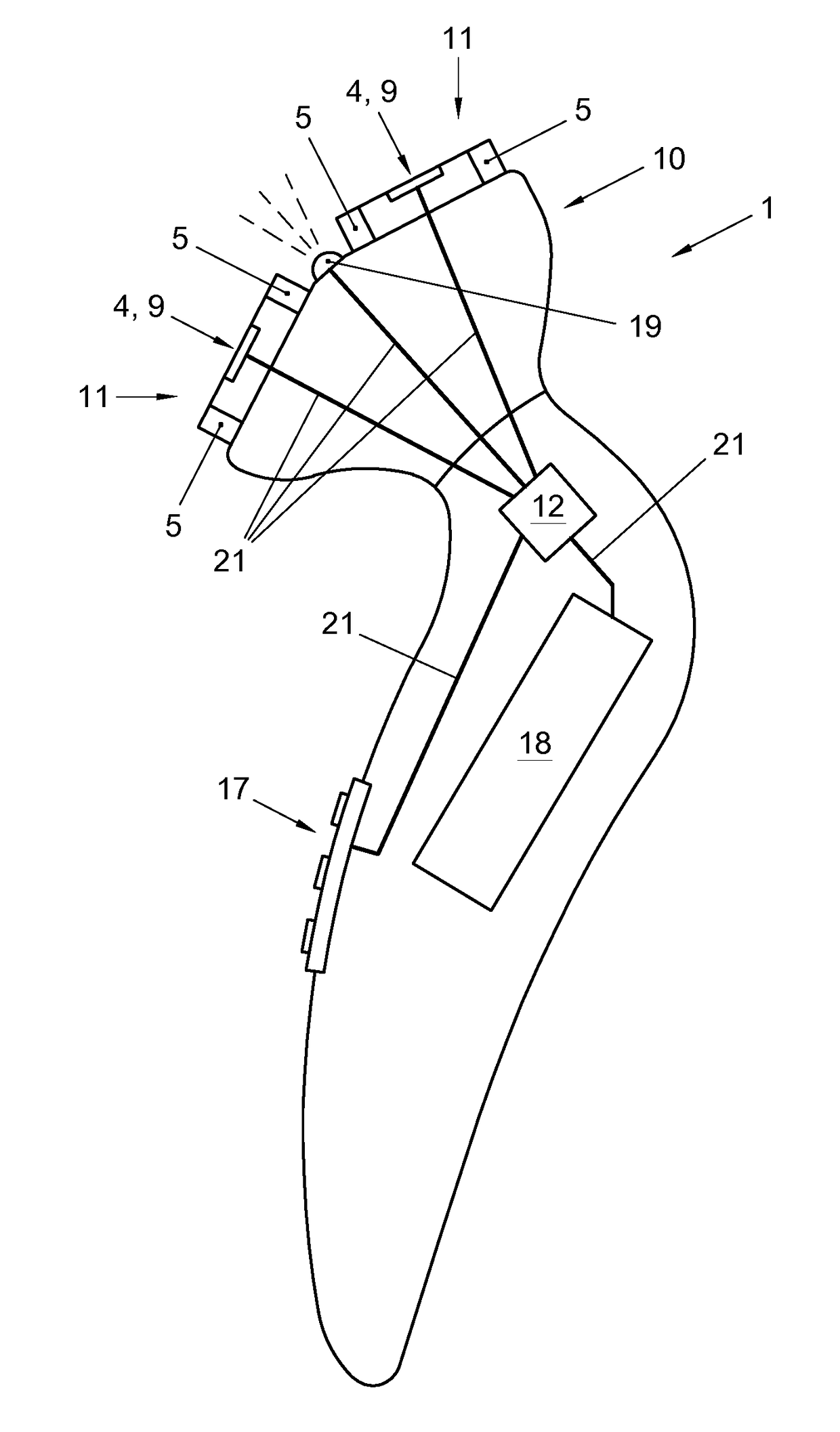
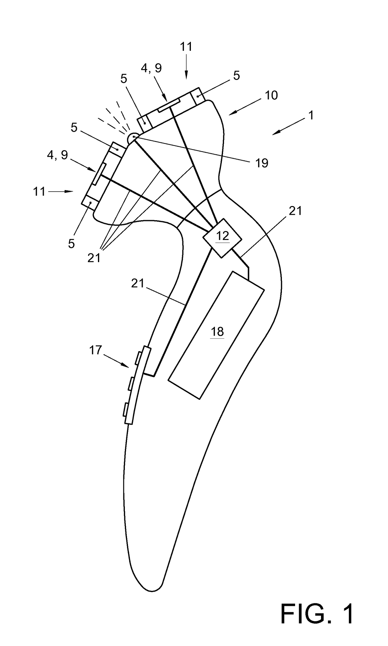
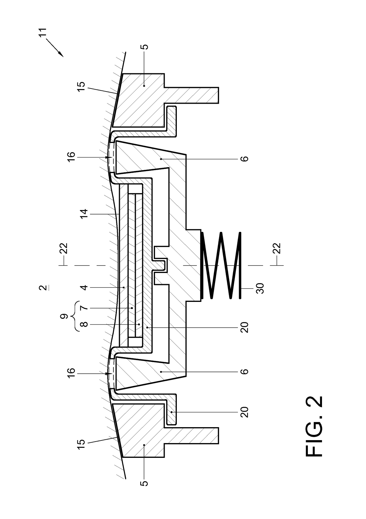
The invention relates to a shaving device for skin hairs. The device comprises a skin-contacting surface structure (14,15), a cutter (6) for cutting hairs in a hair-cutting area (16), a shape-changing smart material (7), and a controller for controlling activation of the shape-changing smart material during use of the shaving device. The shape-changing smart material is configured, arranged and effective to adapt the relative position and/or relative orientation between at least part of the skin-contacting surface structure (14) and at least part of the hair-cutting area (16).

Description

FIELD OF THE INVENTION[0001]The invention relates to a shaving device for skin hairs, which shaving device comprises:[0002]a skin-contacting structure comprising a skin-contacting surface structure for contacting a portion of skin during shaving of said skin by the shaving device; and[0003]a cutter for cutting hairs of said skin portion being contacted by said skin-contacting surface structure, said cutting taking place in a hair-cutting area defined by the shaving device.[0004]The invention applies to shaving devices in which the cutter may or may not be driven to move for performing its cutting movements. In the case of shaving devices with cutters being drivable to move, these movements may be of various nature, such as reciprocating translative movement, (reciprocating and / or continuous) rotative movement, or a combination of reciprocating translative movement and (reciprocating and / or continuous) rotative movement. Furthermore, according to the invention, the cutter may be subs...

Claims


Application Information

Patent Timeline
IPC IPC(8): B26B19/38A61B18/20B26B21/22B26B21/44B26B19/14B26B21/40
CPCB26B19/388B26B19/143B26B21/4056A61B18/203B26B21/4018B26B21/443B26B21/222B26B19/38
Inventor HENDRIKS, CORNELIS PETRUSKAUWENBERG, WERNER DANIEL PETRUSVAN DE MOLENGRAAF, ROLAND ALEXANDERMATHEW, DENNYPASTOOR, SANDER THEODOORDEODATUS DRIESSEN, RUFUS EUGENTHURSFIELD, PAUL PHILIPJOHNSON, MARK THOMASBOEKHORST, FREDERICK MARIAWESTERHOF, WILLEM AUKEVAN DEN ENDE, DAAN ANTON
Owner KONINKLJIJKE PHILIPS NV
Why Eureka
Try Eureka