Method for erecting a shuttering framework

a technology of shuttering framework and frame, which is applied in the direction of auxilary members of forms/shuttering/falseworks, shaping building parts, and forming structures. it can solve the problems of time-consuming and wasteful, complex erecting and heavy, and inability to readily reuse timber, etc., to achieve simple and robust attachment, prevent bowing, and time-consuming

Active Publication Date: 2017-10-12
FAST FORM SYST
View PDF4 Cites 8 Cited by
  • Summary
  • Abstract
  • Description
  • Claims
  • Application Information

AI Technical Summary

Benefits of technology

[0010]The method according to the invention is advantageous because it means that a shuttering framework can be erected without the use of a crane. Thus the method is applicable in areas where therein is minimal head room or space and only using minimal tools. It also means that the framework can be erected by hand and quickly. The method also results in a framework which is strong and rigid in both the lateral and vertical directions.
[0019]The braces may be connected to the supports at a fixed point along the length of the supports (i.e. using a bolt through a hole). In such an embodiment the braces are connected to the supports, and then the angle of the supports altered by adjusting the length of the braces. The braces may be slidingly engaged with the supports. In such an embodiment, the braces preferably engage with a longitudinal slot defined within the supports. This means that the supports can be tilted by sliding the braces within the supports, without altering the length of the braces. It also means that the framework can be quickly constructed and then the angle of the framework to the ground refined by adjusting the length of the braces. The braces may engage with a pair of opposing longitudinal slots present within the side walls of the supports. The connection of the braces to the supports can be by any conventional fixing such as screws or bolts etc.
[0020]The ends of the ties are preferably mounted to the supports via brackets or end plates at each end of each tie. The brackets or end plates are preferably arranged at right angles to the tie, and parallel to the support. The end plates or brackets preferably present a flat surface to the support. The end plates or brackets may be bolted to the ends of the ties or welded thereto. The brackets or end plates thereby allow the simple and robust attachment of the ties to the supports. The attachment of the ties to the supports can be by any conventional fixing such as screws or bolts etc.
[0021]The ties are preferably mounted perpendicular to the supports in use. Preferably the ties are mounted to the supports within equal spacing between each tie and its neighbour. This means that the supports are tied in the strongest way possible. This also provides a manner of bracing which is the most effective at preventing bowing of the shuttering board when such boarding is attached to the supports. To further aid this, preferably one of the plurality of ties is mounted at the base of framework, between the first and second supports
[0022]The supports may be channel form, box, or angle in cross section. The ties may be channel form, box or angle in cross section. The joining member may be channel form, box or angle in cross section. These types of cross section provide the necessary strength to the framework, so that the framework does not deform under its own weight, and / or the weight of the material behind the shuttering, such as the concrete.
[0023]The method according to the invention may further comprise the step of fitting a platform to one or more of the supports. This enables workers to stand at height safely on the framework and position the shuttering board, or attend to any other constructional requirement at height.

Problems solved by technology

The timber cannot readily be reused and this system of building is therefore costly, time consuming and wasteful.
This makes them complex to erect and heavy, often requiring the use of cranes or the like.
In tight construction areas, such as where headroom is limited, cranes cannot be used, and therefore pre-manufactured metal frameworks are not appropriate.
Furthermore, when the frames are joined together for example to make a long wall run, a seam line is present in the shuttering board which means the resultant concrete wall is not perfect.

Method used


Image

  • Method for erecting a shuttering framework
  • Method for erecting a shuttering framework
  • Method for erecting a shuttering framework

Examples


Embodiment Construction

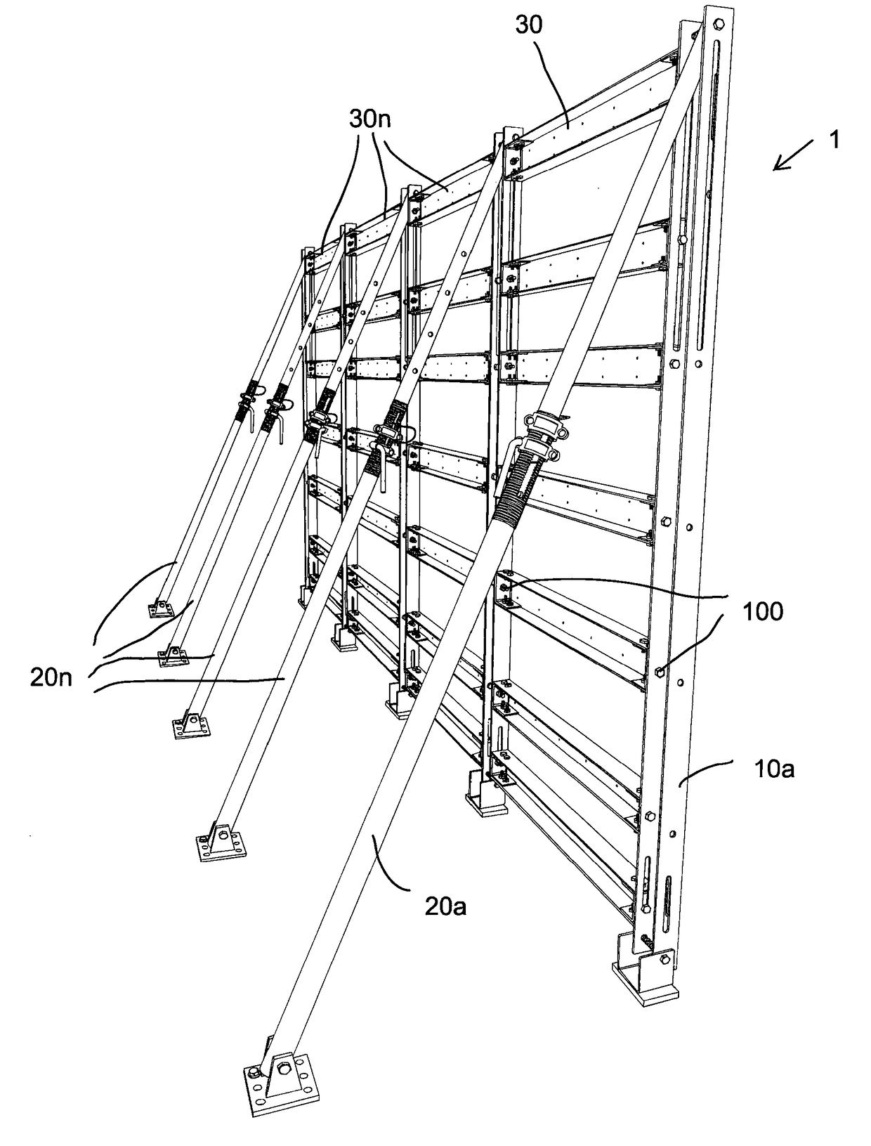
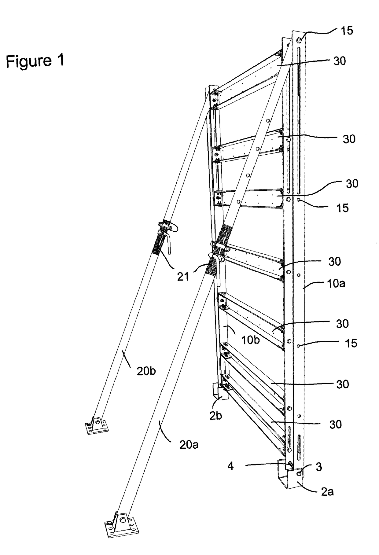
[0038]In FIG. 1 there is shown a shuttering framework erected using an embodiment of the method according to the invention. The framework is generally designated 1. A method for erecting the framework 1 is described as follows.

[0039]Firstly, one end of a first support 10a is fixed to the ground and one end of a first brace 20a is fixed to the ground. In the example provided the first support has a pivotal anchoring bracket 2a fixed to one of its ends, and it is this bracket that fixes to the ground. The bracket 2a is a short length of channel section steel and has a base and two opposing sides. The sides have a hole 3 drilled in them to receive a bolt 4. The base also has a hole drilled in it. A rawl bolt (not shown) is introduced through this hole and is imbedded into the ground surface onto which the bracket 2a is placed. The bolt is tightened and this holds the bracket 2a and thus the first support 10a securely to the ground. In the example shown the first support 10a comprises a...


PUM


Abstract

Disclosed herein is a method for erecting a shuttering framework. The method comprises the steps of a) mounting one end of a first support to the ground or other stationary object and mounting one end of a first brace to the ground or other stationary object, b) attaching the opposite end of the first brace to the opposite end of the first support or to a position between the two ends of the first support, c) repeating a) and b) for a second support and a second brace, and d) mounting a plurality of ties between the first and second supports. Also disclosed herein is a method of casting concrete.

Description

FIELD OF THE INVENTION[0001]The present invention relates to a method for erecting a shuttering framework.BACKGROUND TO THE INVENTION[0002]Shuttering or formwork used within the construction industry conventionally requires the construction of a bespoke timber framework to which shuttering materials are applied. The timber cannot readily be reused and this system of building is therefore costly, time consuming and wasteful.[0003]More extensive metal shuttering systems are in use, particularly in the construction of high walls, but the systems are supplied as pre-manufactured frames with the shuttering board already attached. This makes them complex to erect and heavy, often requiring the use of cranes or the like. In tight construction areas, such as where headroom is limited, cranes cannot be used, and therefore pre-manufactured metal frameworks are not appropriate. Furthermore, when the frames are joined together for example to make a long wall run, a seam line is present in the s...

Claims


Application Information

Patent Timeline
Patent Type & Authority Applications(United States)
IPC IPC(8): E04G11/08E04G17/16E04G17/06E04G17/14
CPCE04G11/08E04G17/14E04G2011/067E04G17/06E04G17/16E04G11/06
Inventor WHITE, TONY
Owner FAST FORM SYST
Why Eureka
Try Eureka