
Wavefront correction method for adaptive optics system

a technology of adaptive optics and wavefront correction, applied in the field of system and method of controlling an adaptive optics system, can solve problems such as significant affecting the quality of acquired images

Active Publication Date: 2017-10-19
CANON KK
View PDF1 Cites 2 Cited by
  • Summary
  • Abstract
  • Description
  • Claims
  • Application Information

AI Technical Summary

Benefits of technology

The patent describes a method for controlling an adaptive optics scanning laser ophthalmoscope (AOSLO) by using wavefront data collected from a fundus being imaged. The method involves calculating a second set of control data based on the wavefront data and a third set of local gain. The control data is then transmitted to the AOSLO to adjust the shape of the illumination wavefront. The technical effect of this method is to improve the accuracy and efficiency of the AOSLO in imaging the fundus.

Problems solved by technology

As the resolution increases, the aberrations of the cornea and the crystalline lens have come to significantly affect the quality of acquired images.

Method used


Image

  • Wavefront correction method for adaptive optics system
  • Wavefront correction method for adaptive optics system
  • Wavefront correction method for adaptive optics system

Examples


first embodiment

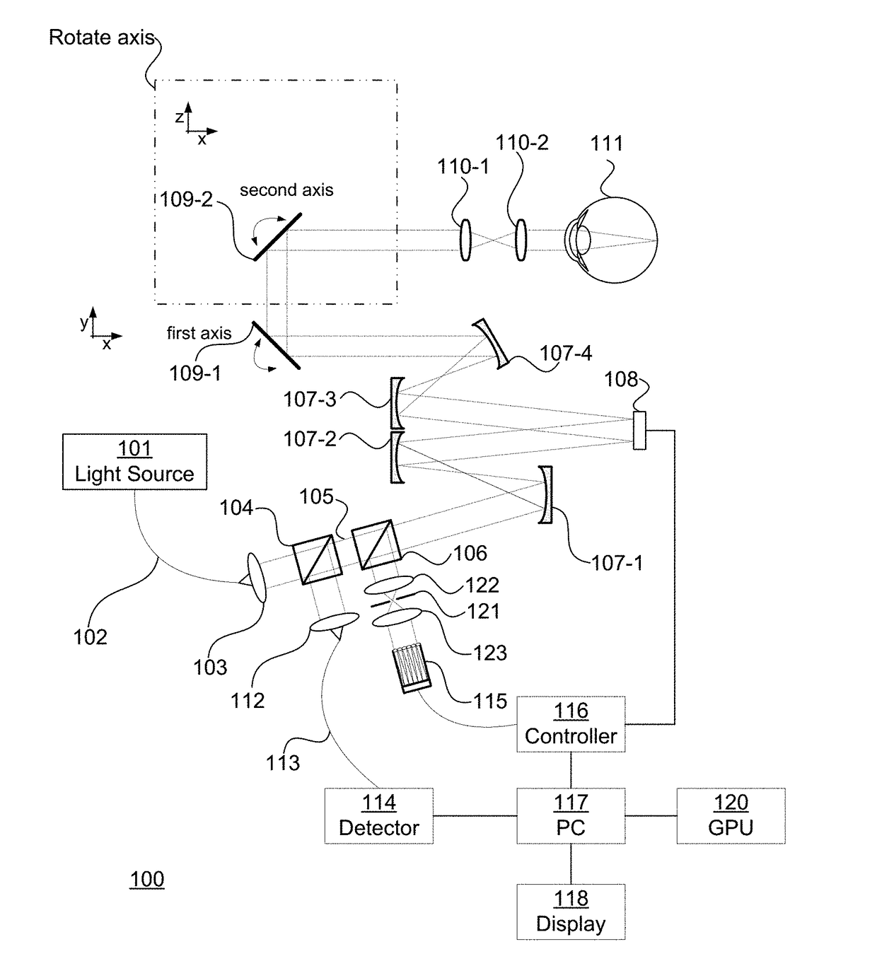
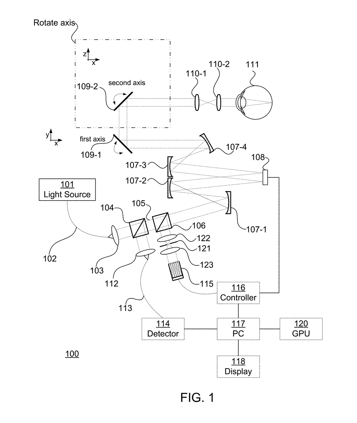
[0029]A first embodiment is described with reference to a fundus image photographing apparatus (ophthalmoscope) such as the photographing apparatus illustrated in FIG. 1.

[0030]Embodiments are directed towards systems, methods, non-transitory computer readable medium, and software which are used in connection with an imaging system such as an ophthalmoscope 100. FIG. 1 is an illustration of an exemplary ophthalmoscope 100. An ophthalmoscope 100 is a system or apparatus for obtaining information about an interior portion of the eye 111 (e.g., the fundus).

[0031]An exemplary embodiment may be a scanning ophthalmoscope. A scanning ophthalmoscope scans a spot across the eye 111. The spot may be a spot of light from a light source 101 that is scanned across the eye 111.

exemplary embodiment 100

[0032]In an exemplary embodiment 100, the spot of light is produced by a light source 101. The light source 101 may be incorporated into the ophthalmoscope 100; alternatively, the ophthalmoscope 100 may include an input for receiving the light source 101. The input for the light source 101 may be a fiber optic input 102 or a free space input (not shown). The light source 101 may be a laser, a broadband light source, or multiple light sources. In an exemplary embodiment, the light source 101 is a super luminescent diode (SLD) light source having a wavelength of 840 nm. The wavelength of the light source 101 is not particularly limited, but the wavelength of the light source 101 for fundus image photographing is suitably set in a range of approximately 800 nm to 1,500 nm in order to reduce glare perceived by a person being inspected and to maintain imaging resolution.

[0033]In an exemplary embodiment, light emitted from the light source 101 passes through a single-mode optical fiber 10...


PUM


Abstract

A method, controller, and medium to control an adaptive optics scanning laser ophthalmoscope. Receiving from the ophthalmoscope a plurality of wavefront elements. Each element may be associated with an area of a beam of light received from a fundus. Each element includes shape data. The shape data represents a shape of a wavefront in a area of the beam. Each element includes status data. The status data is a confidence indicator of ability of the shape data to represent the shape of the wavefront with a particular level of accuracy. Calculating control data based on the shape data in the wavefront data and local gain. The local gain includes local gain elements. Each local gain elements is adjusted based on status data. Using the control data to adjust a shape of an illumination wavefront of an illumination beam used to illuminate the fundus.

Description

BACKGROUNDField of Art[0001]The present disclosure relates to a system and method for controlling an adaptive optics system for an ophthalmic apparatus.Description of the Related Art[0002]Ophthalmoscopes, ophthalmic image pickup apparatuses, fundus imaging systems such as: scanning laser ophthalmoscopes (SLOs) that irradiate the fundus with a laser in two dimensions; and optical coherence tomographs (OCTs) that utilizes the interference of low coherence light have been developed and commercialized. Thus, SLOs and OCTs have become important tools for the study of the human fundus in both normal and diseased eyes.[0003]The resolution of such ophthalmic image pickup apparatuses has recently been improved by, for example, achieving high numerical aperture (NA) of irradiation laser light. However, when an image of the fundus is to be acquired, the image must be acquired through optical tissues including the cornea and the crystalline lens. As the resolution increases, the aberrations of ...

Claims


Application Information

Patent Timeline
Patent Type & Authority Applications(United States)
IPC IPC(8): A61B3/12A61B3/10A61B3/00G02B27/09G02B27/00
CPCA61B3/1225A61B3/1025G02B27/0068A61B3/0025G02B27/0927A61B3/1015A61B3/14
Inventor NOZATO, KOJI
Owner CANON KK
Learn More