
Aircraft ceiling liner element with a carrier platform

a carrier platform and aircraft ceiling liner technology, applied in the direction of aircraft indicators, fuselages, entertainment/communication arrangements, etc., can solve the problem of not being able to take up additional loads, etc., and achieve the effect of convenient configuration, high flexibility, and efficient utilization of spa

Active Publication Date: 2017-10-19
AIRBUS OPERATIONS GMBH
View PDF0 Cites 3 Cited by
  • Summary
  • Abstract
  • Description
  • Claims
  • Application Information

AI Technical Summary

Benefits of technology

The proposed aircraft ceiling liner element allows for the attachment of different modular units, such as storage compartments or display monitors, in an efficient and flexible manner. This results in a more efficient use of space in the aircraft cabin and allows for easy customization to different usage requirements. The modular units can be easily detached and interchanged with each other, making the receptacle and stowage space option provided by the aircraft ceiling liner system easily adaptable and configured for the respective use of the aircraft.

Problems solved by technology

Since low weight is essential for such standard aircraft ceiling liner elements, these are not envisaged to take up additional loads.

Method used


Image

  • Aircraft ceiling liner element with a carrier platform
  • Aircraft ceiling liner element with a carrier platform
  • Aircraft ceiling liner element with a carrier platform

Examples


first embodiment

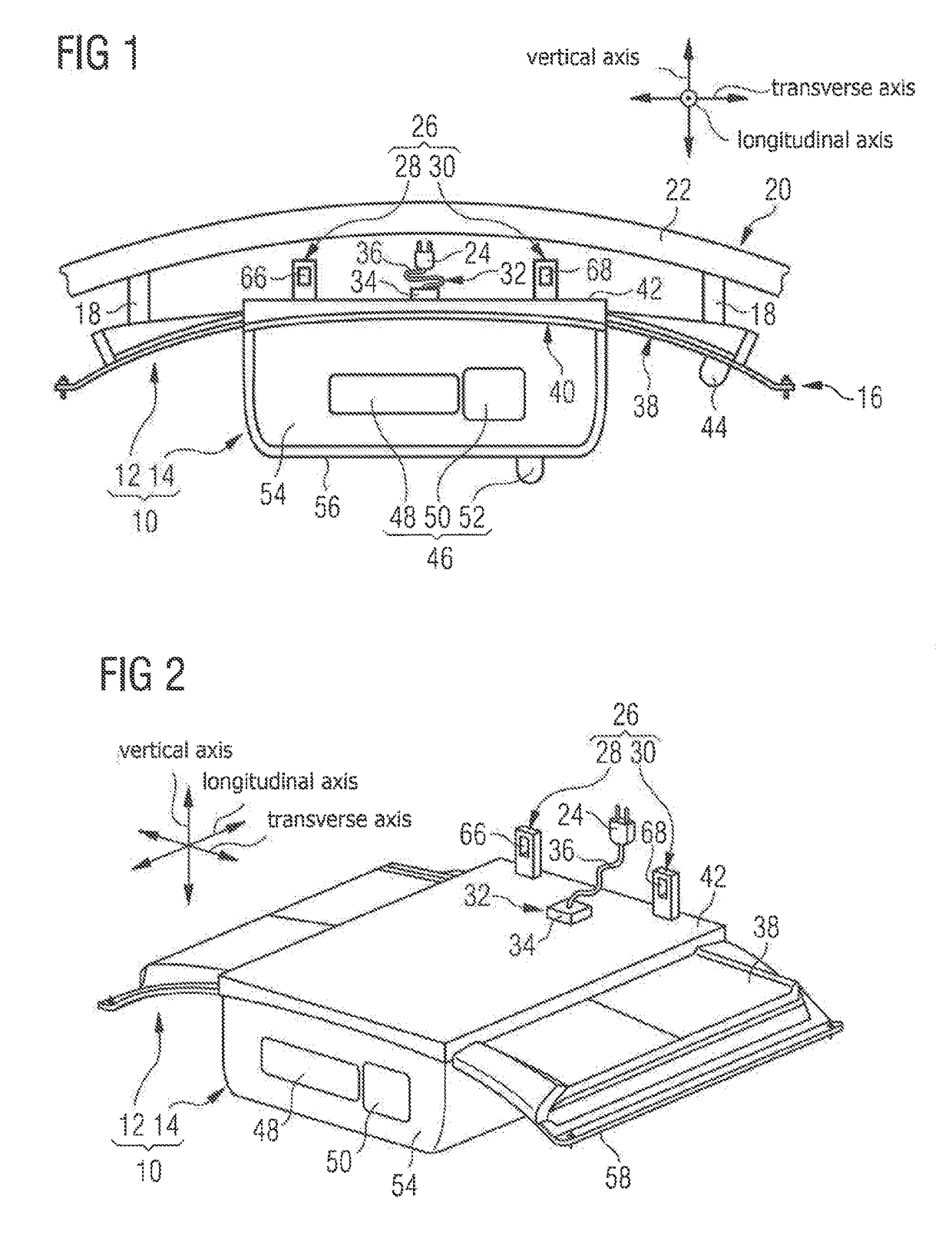
[0056]FIG. 1 shows an aircraft ceiling liner system 10 installed in an aircraft. The aircraft ceiling liner system 10 comprises an aircraft ceiling liner element 12 and a modular unit 14 attached thereto, which is attached detachably, in a load-transferring manner and interchangeably with another modular unit to a carrier platform 16 of the aircraft ceiling liner element 12.

[0057]The carrier platform 16 is configured to form a part of an aircraft ceiling liner. A mounting 18 of the aircraft ceiling liner element 12 fitted on the carrier platform 16 is connected to a primary structure 20 of the aircraft. The mounting 18 is provided in the form of a suspension, which connects the carrier platform 16 to at least one rib 22 of the primary structure 20 of the aircraft.

[0058]FIG. 2 shows a top view in perspective of the aircraft ceiling liner system 10 shown in FIG. 1, in which view the mounting 18 connecting the carrier platform 16 to the primary structure 20 of the aircraft is not shown...

second embodiment

[0073]FIG. 7 shows an enlarged section of a longitudinal section of the aircraft ceiling liner element 10. Compared with the embodiment previously described, the first and second hinge seat 28, 30 are arranged completely in the recess 40 of the frame element 38. The first and second hinge seat 28, 30 are arranged lying opposite to the inner wall 86 of the recess 40 in such a way that in the fitted state of the modular unit 14 in the aircraft, the first latching element 66, 68 and the second latching element 70, 72 are accessible to a fitter in the opening position of the modular unit 14 via the recess 40, in order to uncouple the first and second latching element 66, 68, 70, 72 from one another. In other words, to detach the modular unit 14 from the carrier platform 16 the fitter can uncouple the first and the second latching element 66, 68, 70, 72 from one another by moving the second latching element 70, 72 against the direction of its preloading.

third embodiment

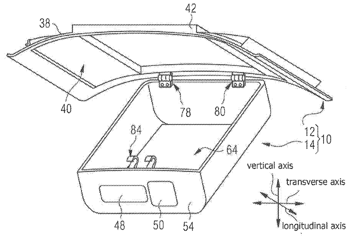
[0074]FIGS. 8 and 9 show the aircraft ceiling liner system 10, in which the modular unit 14 is provided in the form of a second storage compartment with a second storage volume, which is attached to the carrier platform 16 detachably and in a load-transferring manner. The second storage volume is smaller than the first storage volume of the first storage compartment. In FIG. 9 the mounting 18 of the aircraft ceiling liner element 12 is not shown for reasons of clarity.


PUM


Abstract

An aircraft ceiling liner element comprises a load-bearing carrier platform, configured to form a part of an aircraft ceiling liner, and a mounting mounted on the carrier platform, connectable to a primary structure of the aircraft. An electrical connection mounted on the carrier platform is connectable to an electrical supply network of the aircraft. Furthermore, the aircraft ceiling liner element comprises a mechanical interface mounted on the carrier platform, configured to attach various interchangeable modular units detachably and in a load-transferring manner to the carrier platform, and an electrical interface mounted on the carrier platform, which interface is configured to create an electrical connection between the modular unit and the carrier platform.

Description

CROSS REFERENCE TO RELATED APPLICATIONS[0001]This application claims priority to German Patent Application No. 10 2016 206 383.9 filed on Apr. 15, 2016, the entirety of which is incorporated herein by reference.FIELD OF THE INVENTION[0002]The invention relates to an aircraft ceiling liner element, an aircraft ceiling liner system and a method for the installation of such an aircraft ceiling liner system in an aircraft.[0003]The flexible use of passenger aircraft is a requirement that is steadily growing in importance, especially for single-aisle passenger aircraft. Passenger aircraft are to be used accordingly for different purposes, such as for short-, medium- and long-haul flights, for example, as well as for flights over land and water. Depending on the type of use of the passenger aircraft, the items of equipment necessary for the respective deployments vary and must be carried in stowage spaces of the passenger aircraft envisaged for these.[0004]Passenger aircraft currently in ...

Claims


Application Information

Patent Timeline
Patent Type & Authority Applications(United States)
IPC IPC(8): B64D11/00B64D45/00B64C1/22
CPCB64D11/003B64C1/22B64D45/00B64C1/066B64D11/0015
Inventor SCHNEIDER, UWE
Owner AIRBUS OPERATIONS GMBH
Learn More