Reel drive assembly

a technology of reel drive and assembly, which is applied in the direction of cable-laying vessels, pipes, nails, etc., can solve the problems of time-consuming and expensive, cumbersome relocating of reel drive assemblies, damage to assembly components, etc., to facilitate easy assembly and/or disassembly of modular reel drive assemblies, and facilitate the mounting of the reel hub adapter support modul

Active Publication Date: 2017-10-19
ALFRED CHEYNE ENG
View PDF10 Cites 0 Cited by
  • Summary
  • Abstract
  • Description
  • Claims
  • Application Information

AI Technical Summary

Benefits of technology

[0062]By providing a reel drive assembly composed of prefabricated functional modules ready for assembly, the modular assembly may facilitate easy assembly, disassembly and transportation of the reel drive assembly.
[0063]The reel hub adapter support module having at least one support pin which is capable of being moved between an operational position and a storage position may facilitate easy assembly and/or disassembly of the modular reel drive assembly.
[0064]The at least one support pin may be located at the retracted storage position during or before transport of the reel hub adapter support module. Alternately or additionally the at least one support pin may be moved to the retracted storage position durin

Problems solved by technology

Relocating reel drive assemblies can be cumbersome, time consuming and expensive as they are required to be sturdy and sufficiently large and heavy to support a wide range of reel diameters, sizes and weights.
Furthermore, altho

Method used


Image

  • Reel drive assembly
  • Reel drive assembly
  • Reel drive assembly

Examples


first embodiment

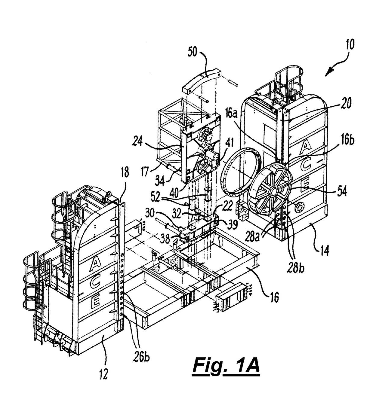
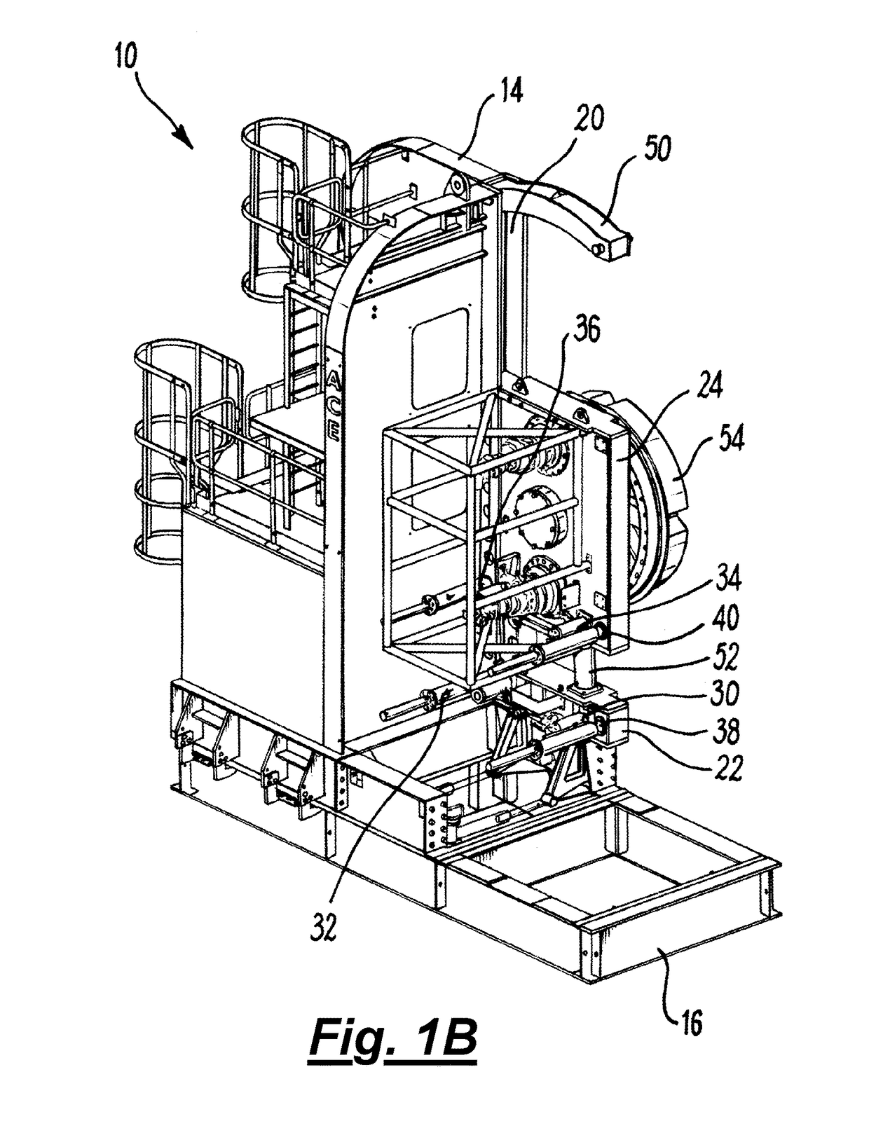
[0118]FIGS. 1A and 1B show a modular reel drive assembly 10 according to the invention. FIG. 1A shows a partially exploded schematic view and FIG. 1B shows an partially assembled view of the modular reel drive assembly with one tower module removed (tower 12) for clarity.

[0119]The modular reel drive assembly 10 can be seen to comprise a first tower module 12 and a second tower module 14 mountable on base frame module 16. When assembled the first and second tower modules 12, 14 are axially aligned and opposed structures which are separated by a gap. Channels 18 and 20 are provided on tower modules 12 and 14 respectively. A reel hub adapter support module comprises a crawler unit 22 and a sliding drive unit 24 is located between the tower modules 12 and 14 and is slideably mounted in the channels 18 and 20. A reel drive hub adapter 54 is mounted on the sliding drive unit 24. The reel drive hub adapter 54 is configured to engage one side of a reel (not shown).

[0120]The crawler unit 22 ...

second embodiment

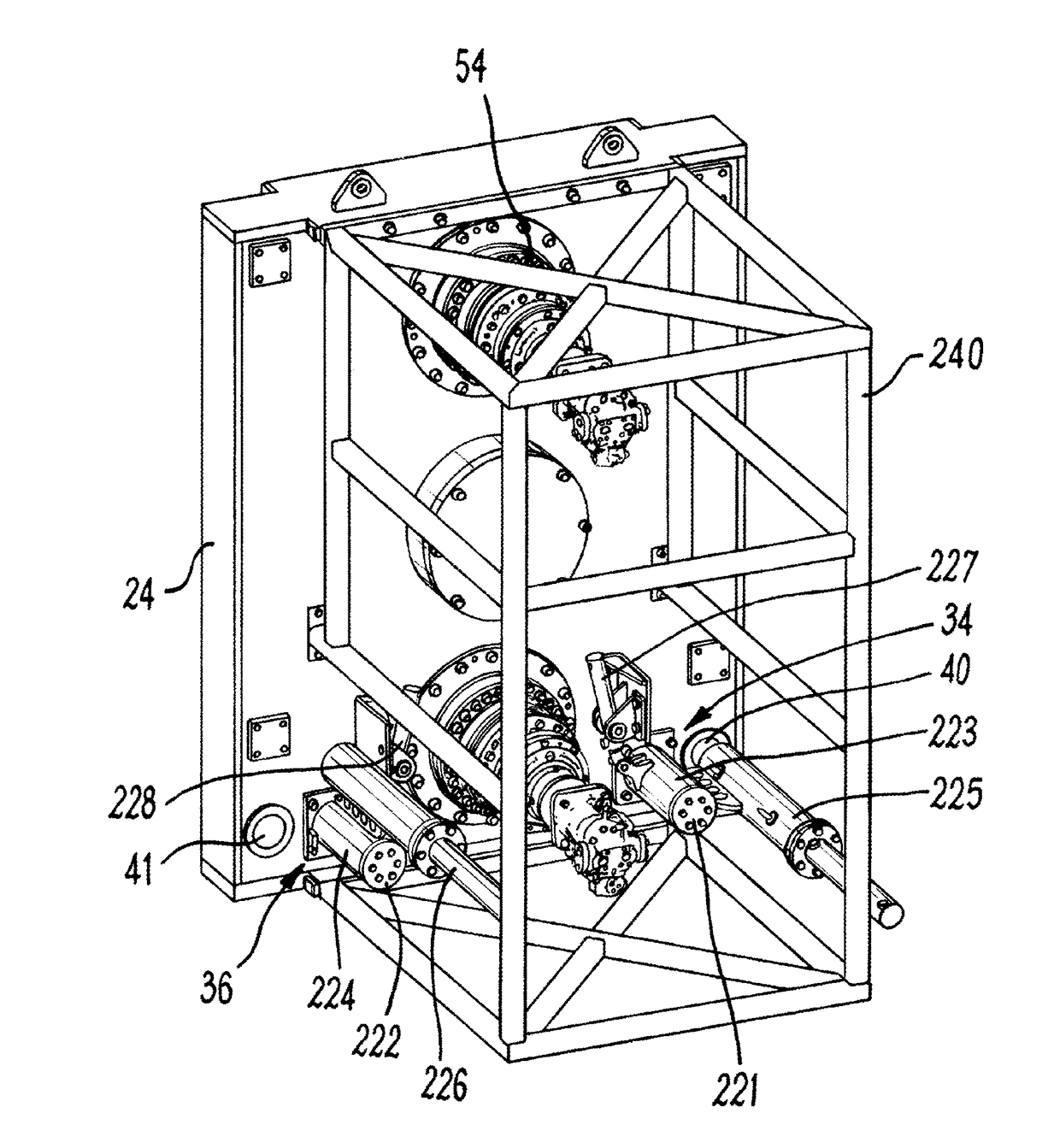
[0124]FIGS. 2a and 2b show the sliding drive unit 24 of the reel hub support assembly according to the invention, shown in perspective and profile views. Hydraulic units 34 and 36 are pivotally mounted on the sliding drive unit 24. The hydraulic units 34 and 36 comprise support members 221 and 222, sleeve members 223 and 224, support pin hydraulic cylinders 225 and 226 and positioning hydraulic cylinders 227 and 228 respectively.

[0125]The support member 221 of the hydraulic unit 34 is affixed to the sliding drive unit 24 and secures the hydraulic unit 34 to the sliding drive unit 24. The support member 221 is secured to the sliding drive unit using bolts. This is merely an example and any other manner of affixing the support member 221 to the sliding drive unit may be used, such as welding if the material is suitable.

[0126]The sleeve member 223 is affixed to the support pin hydraulic cylinder 225 and is configured to be rotationally mounted on the support member 221. The positioning...


PUM


Abstract

A modular reel drive assembly comprises two reel drive tower modules (12, 14), a reel hub adapter (54) and a reel hub adapter support module (22, 24). The hub adapter support module (22, 24) comprises at least one support pin which is configured to be movable between a storage position in which the at least one support pin is not aligned with at least one aperture (38, 39, 40, 41) on the hub adapter support module (22, 24) and an operational position in which the support pin is aligned with at least one aperture (38, 39, 40, 41) on the hub adapter support module (22, 24).

Description

[0001]The present invention relates to a reel drive assembly used to spool cables and other lines onto and off reel drums, and in particular to a modular reel drive assembly. Aspects of the invention include a modular reel drive assembly including an improved reel hub adapter support assembly and a method of use.BACKGROUND TO THE INVENTION[0002]Reel drive assemblies are required to perform a range of tasks including winding, reeling, spooling, lifting and lowering lines such as cable, rope, wire, umbilicals, flowlines, hoses, pipes, cords, or conduits onto or from a reel.[0003]Typically, reel drive assemblies work in pairs with each assembly utilising a reel hub adapter to engage with one side wall flange of the reel to support and / or drive the reel. The reel drive assemblies generally comprise vertical hydraulic cylinders or jacks to lift the reel out of a cradle to allow the reel to rotate or to be driven during spooling or unspooling onto or off the reel.[0004]U.S. Pat. No. 5,875...

Claims


Application Information

Patent Timeline
IPC IPC(8): B65H49/32
CPCB65H49/32B63B35/00B63B35/03B63B35/04B65H54/553B65H67/00F16L1/203B65H49/26B65H49/36B66D1/28B65H49/321B65H49/327B65H49/38B66D5/00B66D5/26F16B15/00F16M11/04F16M11/046F16M2200/02
Inventor NADAGOUDA, NISHANT
Owner ALFRED CHEYNE ENG
Why Eureka
Try Eureka