Turbine impeller

Inactive Publication Date: 2017-10-19
HONDA MOTOR CO LTD
View PDF12 Cites 3 Cited by
  • Summary
  • Abstract
  • Description
  • Claims
  • Application Information

AI Technical Summary

Benefits of technology

The present invention provides a turbine impeller that can efficiently guide the exhaust gases and has high energy conversion efficiency. This results in a broader velocity range for the exhaust gases and ensures a proper angle of attack.

Problems solved by technology

However, a shape of a blade front end of an existing turbine impeller has the following problem: in a case in which an inflow velocity of exhaust changes to an intermediate velocity or low velocity, it is difficult to ensure a proper angle of attack, and the energy conversion efficiency is unfavorable.

Method used


Image

  • Turbine impeller
  • Turbine impeller
  • Turbine impeller

Examples


modified example

[0086]The turbine impeller 5 of the present implementation manner is explained in the foregoing, but a shape of the front edge portion 62 of the blade component 60 can be modified like a front edge portion 262 shown in FIG. 14(B). A turbine impeller 205 is specifically explained below by using accompanying drawings. FIG. 14(A) and FIG. 14(B) are three-dimensional diagrams for illustrating a modified example of a front edge portion of a turbine impeller according to the present implementation manner.

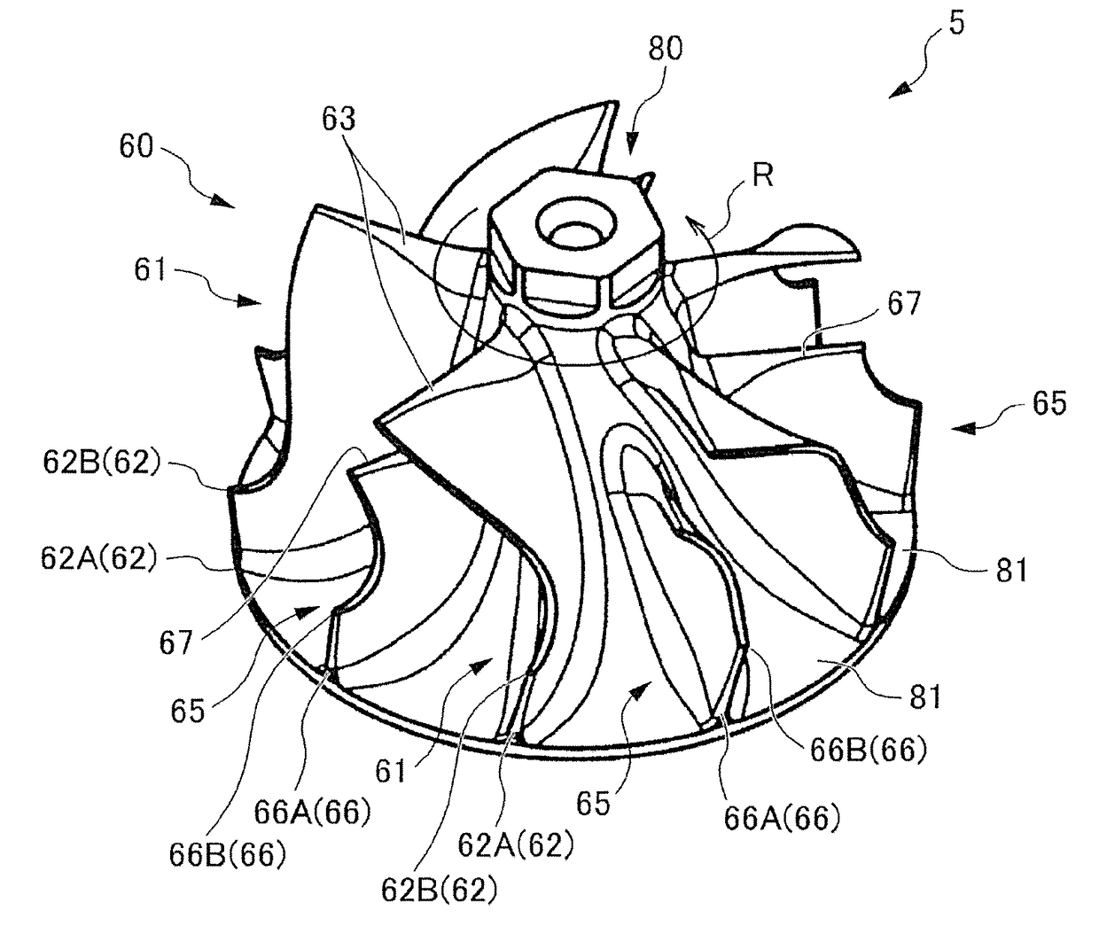
[0087]First, a plate-shaped component is mounted at the rotor 80 and machined into the blade component 60 shown in FIG. 14(A). Hence, a front end of the front edge portion 62 (66) of the blade component 60 is configured approximately the same as an outer circumferential surface 82 of the rotor 80 in a radial direction, and the front edge portion 62 is formed into a planar and angular shape.

[0088]Subsequently, a shaping process is performed on a connection portion (a blade root) between th...


PUM


Abstract

A turbine impeller supplies a high-pressure fluid through a scroll flow route and / or a exhaust supply port of a fixed nozzle and includes: blade components converting the fluid into a rotational force; and a rotor, configured with the blade components and can rotate around a specified rotational axis, wherein a direction, relative to a gas relative inflow velocity of the rotor, specified by using the fluid supply port as a starting point and subtracting a rotational velocity component of the rotor from a supply velocity component of the fluid is set to not intersect with the rotational axis of the rotor; and a shape, from a halfway portion to a front edge portion, of the blade component inclines, relative to a direction from a center of the rotor to an upstream portion of the blade component, toward front side of a rotating direction of the rotor by a specified angle.

Description

CROSS-REFERENCE TO RELATED APPLICATION[0001]This application claims the priority benefit of Japan application serial no. 2016-083767, filed on Apr. 19, 2016. The entirety of the above-mentioned patent application is hereby incorporated by reference herein and made a part of this specification.BACKGROUND OF THE INVENTION1. Field of the Invention[0002]The present invention relates to a turbine impeller.2. Description of Related Art[0003]In the past, as a turbine impeller mounted in a flow route of an internal combustion engine (hereinafter referred to as an engine), the following turbine impeller is known: the turbine impeller is formed in manner of making an orientation of a front end shape of a blade of the turbine impeller consistent to an inflow direction of a gas relative inflow velocity V of a velocity triangle as follows, and the velocity triangle is formed by an inflow velocity C of exhaust that flows into an inlet of a movable blade, a rotational velocity U of the movable bla...

Claims


Application Information

Patent Timeline
IPC IPC(8): F02C6/12F04D25/04F01D5/14
CPCF02C6/12F01D5/147F04D25/04F01D1/22F01D5/141F01D5/048F04D25/024F05D2220/40
Inventor KUNO, NAOKIITOH, NAOKI
Owner HONDA MOTOR CO LTD
Why Eureka
Try Eureka