Dye-sensitized photoelectric conversion element

Inactive Publication Date: 2015-05-14
ZEON CORP +1
View PDF4 Cites 3 Cited by
  • Summary
  • Abstract
  • Description
  • Claims
  • Application Information

AI Technical Summary

Benefits of technology

The present invention is related to a new electrolyte solution that is efficient in converting energy. The invention involves a specific composition of an aliphatic guarternary ammonium ion, an imidazolium ion, and iodide ion dissolved in an organic solvent. The use of this specific electrolyte solution results in high energy conversion efficiency even with reduced amounts of iodine added. The specific electrolytes have been found to accelerate electron transfer between iodide ions, which is different from the case where a redox couple is present. The use of a metal as the conductive layer of the photoelectrode or counter electrode layer is also possible because iodine is not corrosive with the metal. The electrolyte solution is transparent, which is a benefit for energy conversion.

Problems solved by technology

Accordingly, the solar cell of the solid junction type has a defect in a high cost of a plant.
Therefore, the energy payback time is relatively long.
However, the practically used redox couple is limited to only the combination of iodine (triiodide ion in the solution) and iodide (iodide ion in the solution) from the viewpoint of high energy conversion efficiency.
It is difficult to obtain sufficiently high energy conversion efficiency with a redox couple other than the combination of iodine and iodide.

Method used


Image

  • Dye-sensitized photoelectric conversion element
  • Dye-sensitized photoelectric conversion element
  • Dye-sensitized photoelectric conversion element

Examples


example 1

(1) Preparation of Electrolyte Solution

[0167]In a measuring flask of 5 mL, 0.066 g of N-methylbenzimidazole, 0.738 g of tetrabutylammonium iodide, 0.532 g of 1,3-butylmethylimidazolium iodide, and 0.58 g of guanidine thiocyanate was placed. Propylene carbonate was added to the mixture to give a total amount of 5 mL. The mixture was stirred with vibration for 1 hour in an ultrasonic wave washing machine. The flask was placed in a dark calm place for 24 hours to prepare an electrolyte solution containing no iodine.

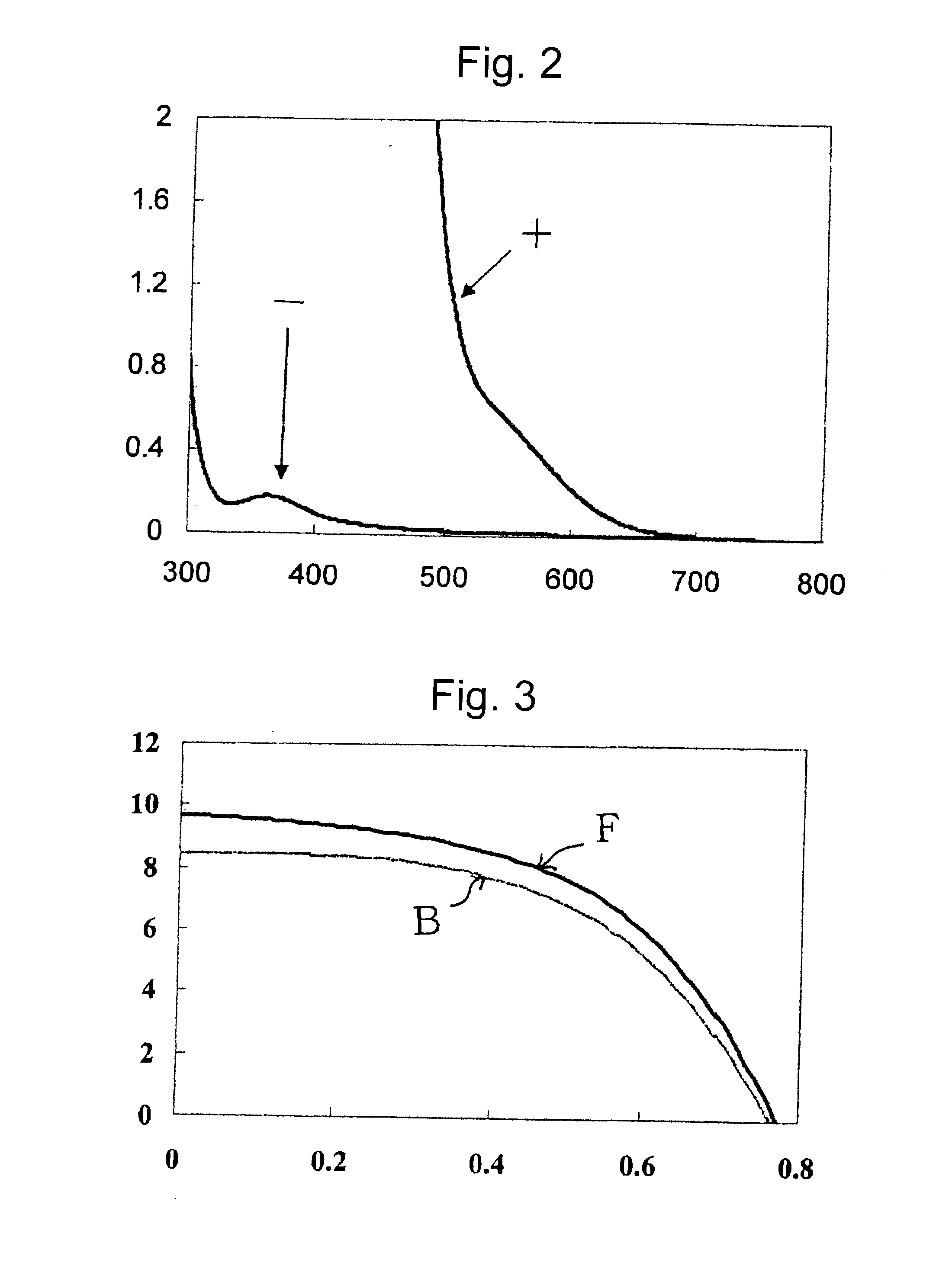
[0168]A reference electrolyte solution containing iodine was prepared adding 0.04 M of iodine to the above-prepared electrolyte solution. Absorption spectra of the electrolyte solution containing no iodine and the solution containing iodine were measured at optical pass length of 1 mm. The results are shown in FIG. 2.

[0169]FIG. 2 is absorption spectra of the electrolyte solution containing no iodine (−) and the solution containing iodine (+), which is in the form of triiodid...

example 2

[0186]A dye-sensitized photoelectric conversion device was prepared in the same manner as in Example 1, except that γ-butyrolactone was used in place of propylene carbonate in preparation of electrolyte solution of Example 1 (1).

[0187]The obtained dye-sensitized photoelectric conversion device was evaluated in the same manner as in Example 1 (6). The obtained output current was excellent in analogy to that of Example 1. Further, the result of light incident on the front side is analogous to that of light incident on the backside.

[0188]Further, the dye-sensitized photoelectric conversion device was evaluated in the same manner as in Example 1 (6), except that output current was measured while inclining the device at 60° to light. The output current was compared with that of light perpendicularly incident to the device. The former result was 80% of the latter result.

[0189]The durability of the dye-sensitized photoelectric conversion device was evaluated in the same manner as in Exampl...

example 3

[0190]A dye-sensitized photoelectric conversion device was prepared in the same manner as in Example 1, except that 3-methoxypropionitrile was used in place of propylene carbonate in preparation of electrolyte solution of Example 1 (1).

[0191]The obtained dye-sensitized photoelectric conversion device was evaluated in the same manner as in Example 1 (6). The obtained output current was excellent in analogy to that of Example 1. Further, the result of light incident on the front side is analogous to that of light incident on the backside.

[0192]The durability of the dye-sensitized photoelectric conversion device was evaluated in the same manner as in Example 1 (7). The output current was reduced by about 6% after the durability test.


PUM


Abstract

A dye-sensitized photoelectric conversion device of the present invention has high energy conversion efficiency, even if the amount of iodine added into the electrolyte solution is significantly reduced. The dye-sensitized photoelectric conversion device has a porous photoelectrode layer comprising dye-sensitized semiconductor particles, an electrolyte solution layer, and a counter electrode layer in order. The electrolyte solution layer comprises an electrolyte solution containing 0.05 to 5 M of an aliphatic quarternary ammonium ion, 0.05 to 5 M of an imidazolium ion, and 0.1 to 10 M of iodide ion. The ions are dissolved in an organic solvent. Consequently, the amount of iodine added into the electrolyte solution can be reduced significantly.

Description

FIELD OF THE INVENTION[0001]The present invention relates to a photoelectric conversion device of a dye-sensitized type.BACKGROUND OF THE INVENTION[0002]An intensive research has recently been conducted into a solar cell of a solid p-n junction type, which is one of photoelectric conversion devices for converting solar energy into electric power. The solar cell of the solid junction type uses silicon crystals, a thin amorphous silicon film, or a thin multi-layered film comprising a semiconductor of a non-silicon compound.[0003]The solar cell of the solid junction type has been prepared under high-temperature or vacuum conditions. Accordingly, the solar cell of the solid junction type has a defect in a high cost of a plant. Therefore, the energy payback time is relatively long.[0004]A solar cell of an organic type has been developed with the anticipation of the coming generation of the solar cell. The organic solar cell can be prepared under conditions of low temperature at a low cos...

Claims


Application Information

Patent Timeline
IPC IPC(8): H01G9/20
CPCH01G9/2063H01G9/2013H01G9/2031H01G9/2059H01G9/2095Y02E10/542H10K2102/103
Inventor MIYASAKA, TSUTOMUIKEGAMI, MASASHI
Owner ZEON CORP
Why Eureka
Try Eureka