Interstrand short circuit testing of stator winding bars of electric machines

Inactive Publication Date: 2017-10-19
SIEMENS AG
View PDF5 Cites 2 Cited by
  • Summary
  • Abstract
  • Description
  • Claims
  • Application Information

AI Technical Summary

Benefits of technology

The invention is a method and device for checking the insulation of individual strands in a stator winding bar of an electrical machine. This allows for efficient and reliable checking of fully-fabricated stator winding bars, reducing the time and cost compared to previous methods. The apparatus is particularly useful for generators, where stator winding bars can be checked during assembly. The technical effect of this invention is to prevent power loss and ensure correct electrical insulation between strands, leading to improved performance and reliability of the electrical machine.

Problems solved by technology

Like the bending, the desired Roebel-stranding causes mechanical stress, which can have the result that the strand insulation is damaged, and that electrical contacts can occur between individual instances of the strands of a stator winding bar.
These unwanted electrical connections between strands impair the electrical insulation of the strands, and when the machine, which may be a rotating (three-phase) motor or a generator, is operating they lead to a risk of premature failure.
The service life and / or the capacity of the machine is significantly impaired as a result.
This procedure in the prior art was very time-consuming and expensive since for one stator winding bar, which is constructed, for example, from 50 strands that are correspondingly Roebel-stranded together, it is necessary to check each strand for insulation with respect to the other strands within the stator winding bar.
That means that these measurements must already be carried out before the application of the appropriate insulation, that is before installation of the Roebel bars into the laminated stator core, since a measurement is no longer possible at a later time.
As a particular consequence, early damage that occurs, for example, during transport, which only leads to low-resistance connections between the strands when subjected to additional mechanical stress, such as the pressing after installation of the bars, or Roebel bars, into the laminated core, is not detected.
This means that in the prior art it could happen that the time-consuming measurement has not indicated any damage to the insulation between the strands, although said damage is present after installation has been completed.

Method used


Image

  • Interstrand short circuit testing of stator winding bars of electric machines
  • Interstrand short circuit testing of stator winding bars of electric machines
  • Interstrand short circuit testing of stator winding bars of electric machines

Examples


Embodiment Construction

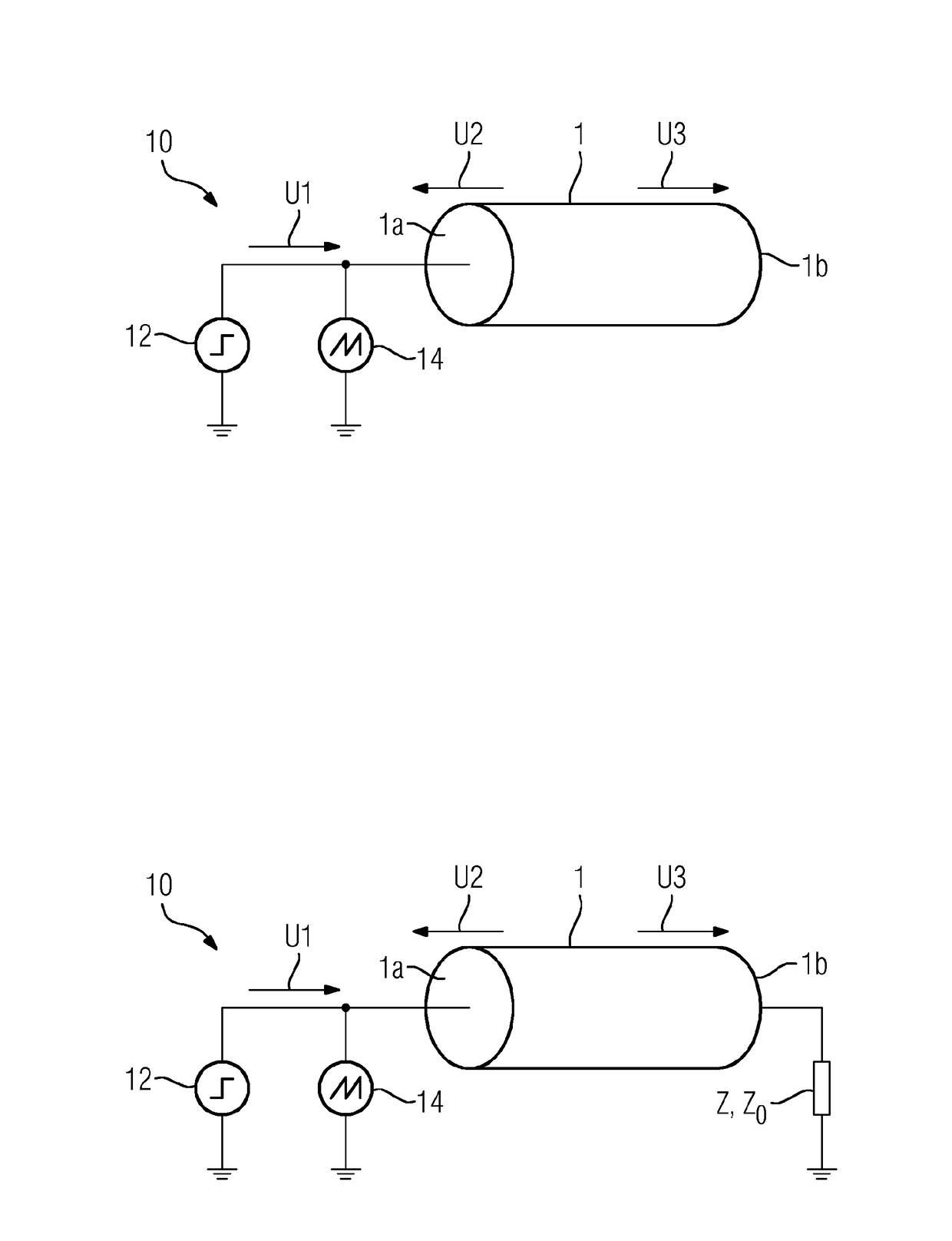
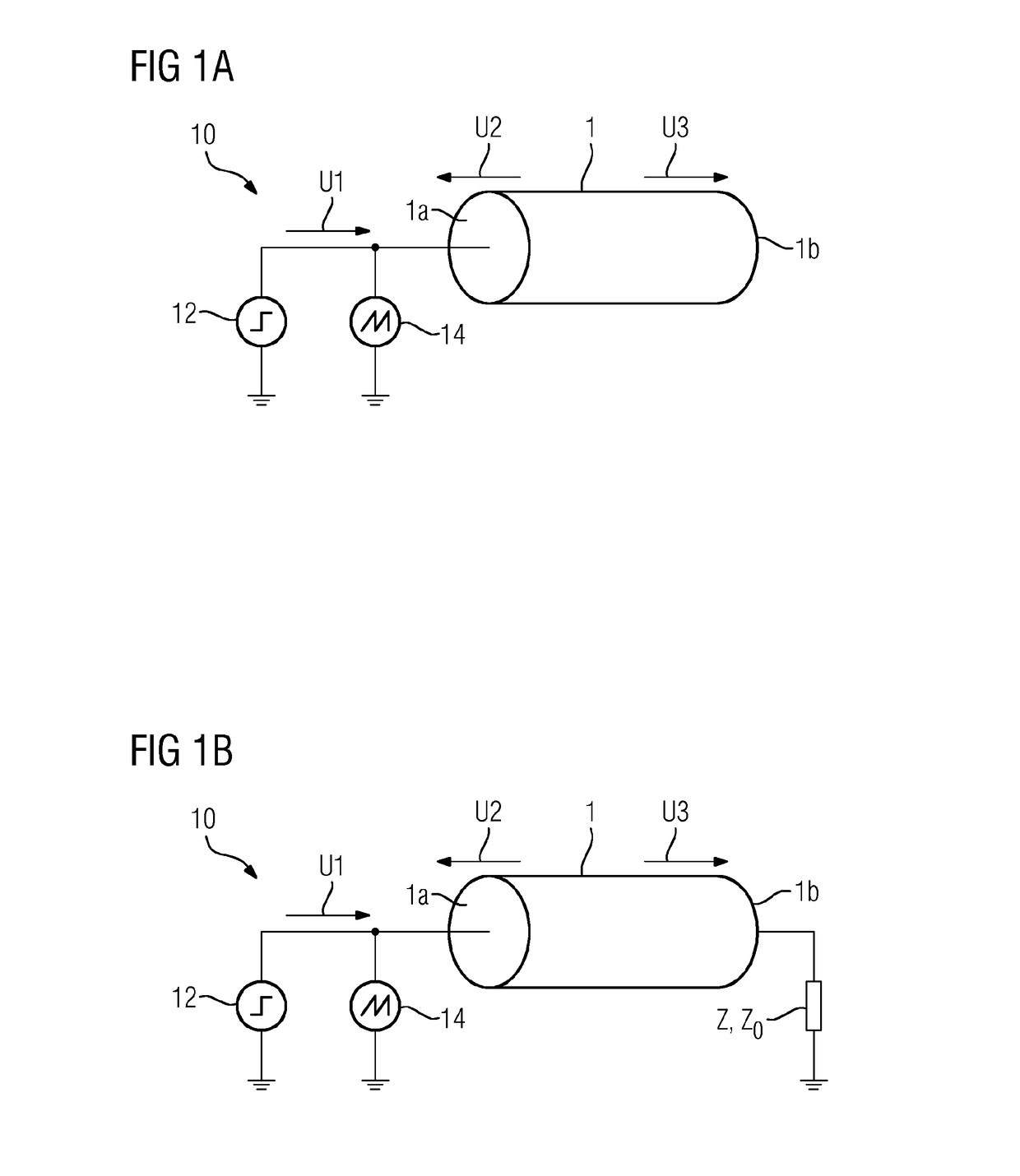
[0029]FIG. 1 shows a first structure for carrying out the method according to the invention. For this purpose, a stator winding bar 1 is subjected at a first segment, in particular at a first end segment 1a, to a test signal U1, there being no termination or short-circuit provided at a second segment of the stator winding bar 1, in particular at its second end segment 1b. The test signal U1 can be provided by a signal source 12. The test signal U1 propagates along the stator winding bar 1. It is advantageous for the test signal U1 to be injected into a multiplicity of the strands within the stator winding bar 1, in order to be able to check a plurality of the strands with one measurement. It is possible, without limitation, for the test signal U1 to be injected into all of the strands of the stator winding bar 1.

[0030]Suitable means for the injection 100 of the test signal as the first step of the method are known to the expert. The injection 100 can thus signify, for example, an el...


PUM


Abstract

A method and an apparatus check a multiplicity of mutually insulated strands in a stator winding bar of an electric machine. The method includes injecting a test signal, determining a first component of the test signal, and comparing at least the first component with a reference signal in order to determine damage to insulation between individual strands of the multiplicity of strands. The apparatus includes a signal source and a measuring apparatus. The method and the apparatus are particularly suitable for checking stator winding bars as are used in a generator and / or an electric motor.

Description

CROSS REFERENCE TO RELATED APPLICATIONS[0001]This application is the US National Stage of International Application No. PCT / EP2014 / 069143 filed Sep. 9, 2014, and claims the benefit thereof. The International Application claims the benefit of European Application No. EP13185685 filed Sep. 24, 2013. All of the applications are incorporated by reference herein in their entirety.FIELD OF INVENTION[0002]The invention relates to a method for checking a multiplicity of mutually insulated strands in a stator winding bar of an electrical machine, and to a corresponding apparatus.BACKGROUND OF INVENTION[0003]In electrical machines, in particular in rotating electrical machines, such as for example motors or generators, what are known as stator winding bars are used in order to homogenize the current density within the electrical machine and to reduce induced eddy currents as far as possible. The rotating machines are constructed for this purpose from a multiplicity of partial conductors or st...

Claims


Application Information

Patent Timeline
IPC IPC(8): G01R31/11G01R31/06G01R31/02
CPCG01R31/11G01R31/025G01R31/06G01R31/1272G01R31/34G01R31/52
Inventor STAUBACH, CHRISTIAN
Owner SIEMENS AG
Why Eureka
Try Eureka