Method for measuring passive intermodulation and measuring device

a passive intermodulation and measurement device technology, applied in the direction of transmission monitoring, transmission monitoring/testing/fault-measurement systems, electrical devices, etc., can solve the problems of adversely affecting the quality of communication, significant influence on the sensitivity of the receiver and thus the quality of the connection, and the measurement device described above often does not permit satisfactory quality testing of the signal transmission path

Active Publication Date: 2017-10-19
ROSENBERGER HOCHFREQUENZTECHNIK GMBH & CO KG
View PDF6 Cites 8 Cited by
  • Summary
  • Abstract
  • Description
  • Claims
  • Application Information

AI Technical Summary

Benefits of technology

[0027]The measuring device may also include a third signal source and a modulator for generating the compensation signa

Problems solved by technology

UE on the other hand, faults in the transmission path can significantly influence the sensitivity of the receivers and thus the quality of the connection.
Some of these interfering signals can fall within the reception band of the BTS and thus adversely affect the quality of the communication.
For example, corrosion in plug connectors, oxide coatings on contacts and metal-metal transitions, impurities in materials a

Method used


Image

  • Method for measuring passive intermodulation and measuring device
  • Method for measuring passive intermodulation and measuring device
  • Method for measuring passive intermodulation and measuring device

Examples


first embodiment

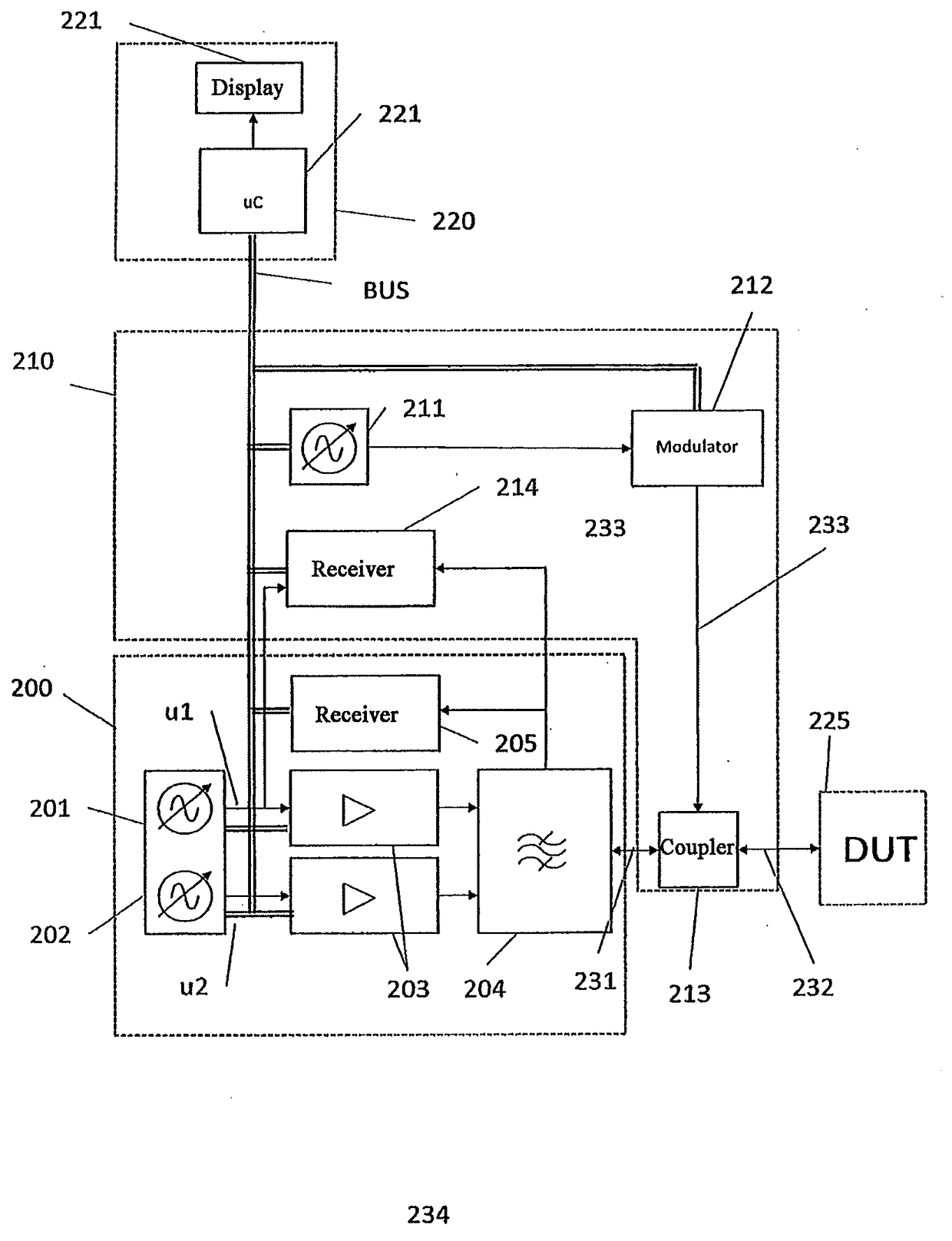
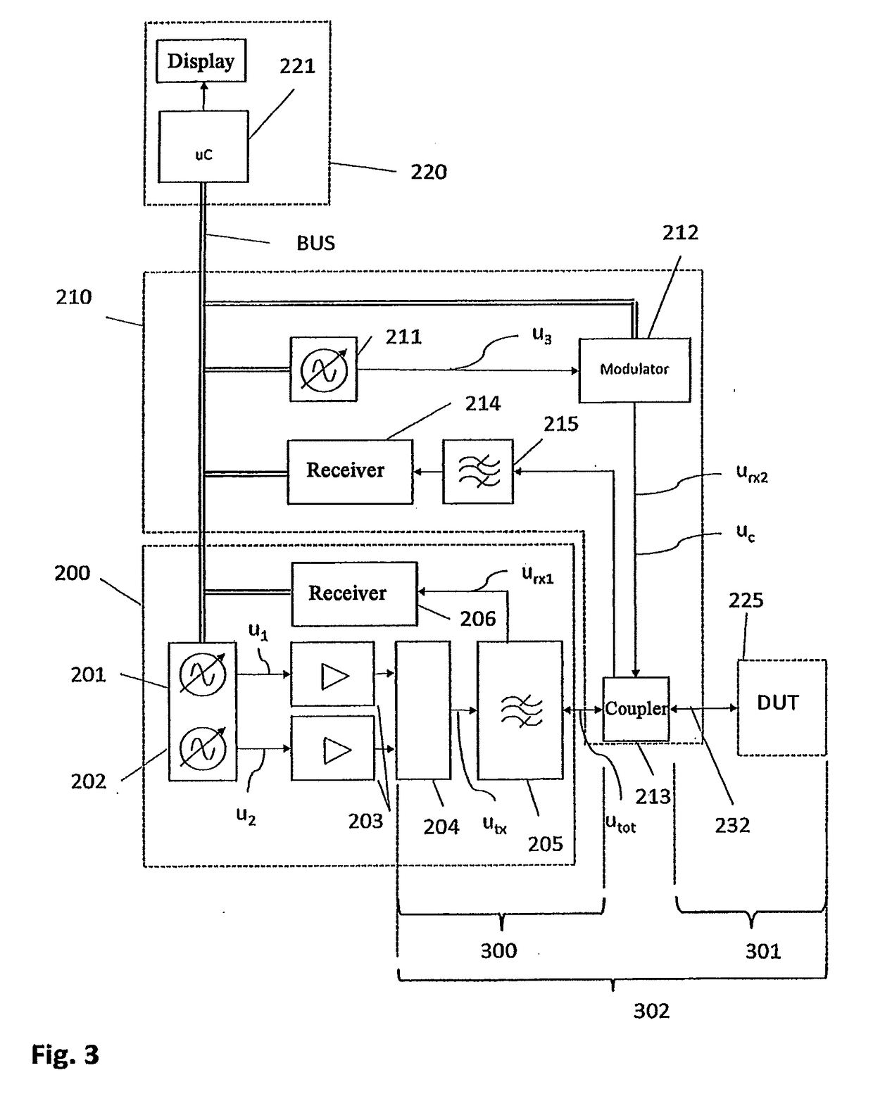
[0074]FIG. 3 is a schematic representation of a measuring device according to the invention for carrying out the method according to the invention for the measurement of PIM with predistortion. This embodiment consists of a measuring unit 200, a predistortion unit 210, a controller unit 220, and a Device Under Test (DUT) 225.

[0075]Measuring unit: the measuring unit 200 consists of at least 2 signal sources 201 and 202, at least 2 amplifiers 203, a combiner 204, a filter 205 and a receiver 206.

[0076]Signal sources: the two signal sources 201 and 202 are connected with a controller unit 220. They generate signals u1(t) and u2(t) which, depending on the embodiment, can be sinusoidal or modulated. Preferably, the two signals have different carrier frequencies f1 and f2.

[0077]Amplifiers: The two signal sources are connected with the two amplifiers 203.

[0078]Combiner: the combiner 204 is connected with the two amplifiers 203 on the one hand, and with the TX path of the filter 205 on the o...

second embodiment

[0112]In the second embodiment, the measuring signal is filtered, wherein only voltages with frequenciesdmin are used to determine the power of rPIM. In this way, a separation of PIM and rPIM is achieved. Because only signals with frequencies>fdDUT are used for the measurement of PIM, a resolution limit of Imin is achieved, which is defined as

lmin=cfdmin2dfdt(15)

[0113]The compensation signal can now be generated on the basis of the power determined for rPIM and introduced into the signal path.


PUM


Abstract

A method for measuring intermodulation produced in a measurement segment of a signal transmission path, by: producing a first. HF signal (u1(t)) and a second HF signal (u2(t)), both having a predetermined frequency progression; feeding the first HF signal (u1(t)) and the second HF signal (u2(t)) to the signal transmission path, wherein an intermodulation signal is produced, which intermodulation signal has a first intermodulation signal component (urPIM(t)) produced in an input segment of the signal transmission path and a second intermodulation signal component (uPIM(t)) produced in the measurement segment of the signal transmission path; producing a compensation signal (uc(t)) in accordance with the first intermodulation signal component (urPIM(t)) produced in the input segment; introducing the compensation signal (uc(t)) into the signal transmission path in order to reduce or cancel out the first intermodulation signal component (urPIM(t)). The invention further relates to a measuring device for performing said method.

Description

BACKGROUND OF THE INVENTION1. Field of the Invention[0001]The present invention relates in general to measuring systems for high frequency communication systems and specifically to measuring devices for measuring passive intermodulation.[0002]In particular, the present invention relates to a method for measuring intermodulation generated in a signal transmission path in which a first HF signal u1(t) with a predetermined frequency progression and a second HF signal u2(t) with a predetermined frequency progression are generated and the first HF signal u1(t) and the second HF signal u2(t) are introduced into the signal transmission path, wherein an intermodulation signal containing intermodulation products is produced in the signal transmission path from the first HF signal u1(t) and the second HF signal u2(t). Such an intermodulation signal can for example contain indications of the location of defective points in the signal transmission path and can therefore be used to locate faults...

Claims


Application Information

Patent Timeline
IPC IPC(8): H04B17/345H04B10/07H04B3/46H04B17/00H04B17/10
CPCH04B17/345H04B17/104H04B10/07H04B3/46H04B17/0085
Inventor ENTSFELLNER, CHRISTIANKAINDL, BENJAMINSCHWAB, MARTIN
Owner ROSENBERGER HOCHFREQUENZTECHNIK GMBH & CO KG
Why Eureka
Try Eureka