Medical device

a medical device and guide wire technology, applied in the field of medical devices, can solve the problems of difficult to perform an injection operation of contrast agents, medicine, or the like via the guide wire lumen, and the opening portion is likely to be wet with blood leaking from the sheath, so as to achieve good image quality, simplified configuration, and high-quality operation of the guide wire w

Active Publication Date: 2017-10-26
TERUMO KK
View PDF0 Cites 8 Cited by
  • Summary
  • Abstract
  • Description
  • Claims
  • Application Information

AI Technical Summary

Benefits of technology

[0008]In the medical device having such a configuration described above, the first hub portion is interlocked, in the airtight manner, with the first shaft proximal portion in which the drive shaft is accommodated, and the second hub portion is interlocked, in an airtight manner, with the second shaft proximal portion into which the guide wire is inserted, and the hub casing collectively covers the first hub portion and the second hub portion. Therefore, it is easy to interchange the guide wire on a hand side during an operation and it is possible to inject a contrast agent, medicine, or the like via the guide wire lumen. Further, since the drive shaft is held in the first shaft proximal portion in the hub casing, the distortion or sliding failure of the drive shaft is unlikely to occur, and thus it is possible to acquire a good-quality image. In addition, since the guide wire is held in the second shaft proximal portion in the hub casing, the distortion or the sliding failure of the guide wire is unlikely to occur in the hub casing, and thus it is possible to achieve a high-quality operation of the guide wire W. In addition, since the first hub portion is interlocked with the first shaft proximal portion in the airtight manner, and the second hub portion is interlocked with the second shaft proximal portion in the airtight manner, the hub casing that collectively covers the first shaft proximal portion, the second shaft proximal portion, the first hub portion, and the second hub portion does not need to have the sealing performance, but can have a simplified configuration, and can realize simplification in the manufacturing process or reduction in costs.
[0009]When the shaft main body portion is provided with two regions having different colors, one region in which the image acquiring lumen is formed and the other region in which the guide wire lumen is formed, it is possible to easily discriminate between the image acquiring lumen and the guide wire lumen and it is easy to insert the guide wire into the guide wire lumen when the guide wire is inserted into the guide wire lumen from an opening portion of the shaft distal portion on the distal side.
[0010]In a case where the axis line of the shaft main body portion in the distal portion of the hub casing is set to the reference line, θ1 represents the inclination of the central axis of the first hub portion with respect to the reference line, θ2 represents the inclination of the central axis of the second hub portion with respect to the reference line, and the relationship of |θ1|>|θ2| is satisfied, even when the guide wire lumen and the opening portion of the image acquiring lumen on the proximal side are close to each other, the first hub portion and the second hub portion are formed in the different directions. Therefore, it is possible to maintain the high operability without the interference of the motion of the drive shaft and the imaging unit via the image acquiring lumen with the operation of the guide wire via the guide wire lumen. In addition, since the relationship of |θ1|>|θ2| is satisfied, it is possible to maintain the operability of the guide wire normally having rigidity higher than that of the drive shaft, to the highest extent.

Problems solved by technology

Therefore, since it is possible for an opening portion of the guide wire lumen on the proximal side to approach a sheath for percutaneously introducing the ultrasound catheter into the blood vessel, the opening portion is likely to be wetted with blood leaking from the sheath.
Therefore, it is difficult to perform an interchange of the guide wire or an injection operation of a contrast agent, medicine, or the like via the guide wire lumen.

Method used


Image

  • Medical device
  • Medical device
  • Medical device

Examples


Embodiment Construction

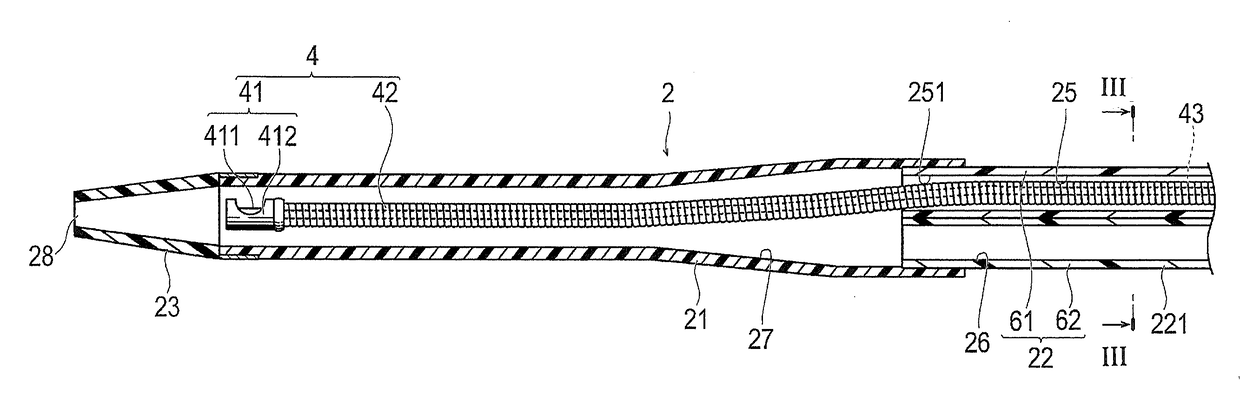
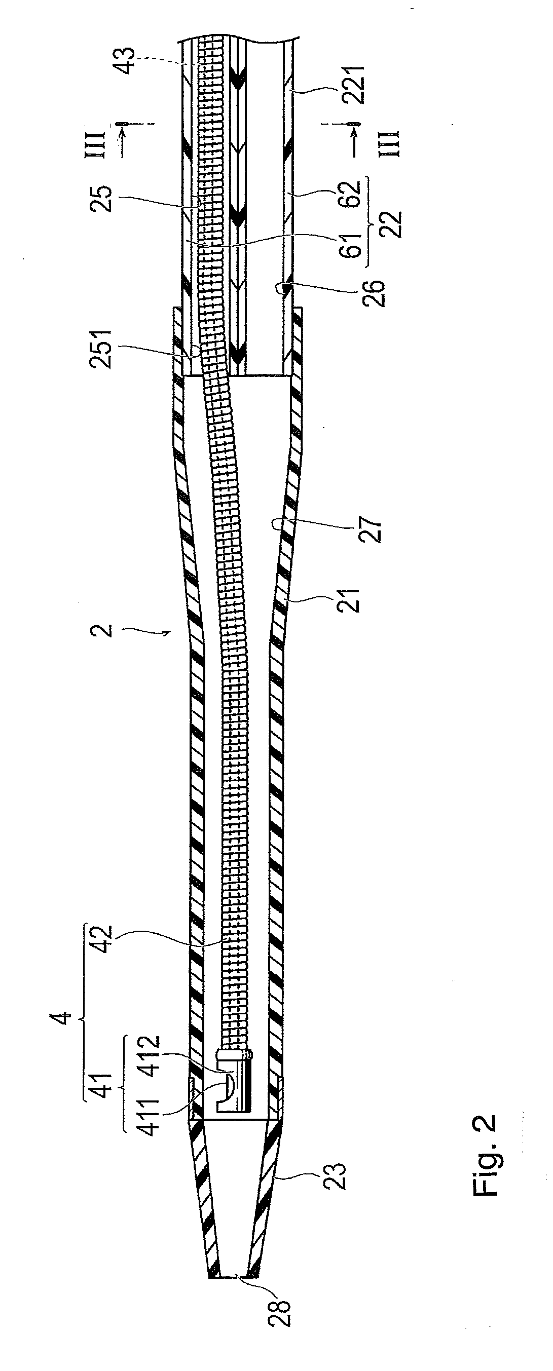
[0030]Set forth below with reference to the accompanying drawing figures is a detailed description of an embodiment of a medical device representing one example of the inventive medical device disclosed here. A dimension ratio in the figures is enlarged depending on the description and the ratio is different from an actual ratio in some cases.

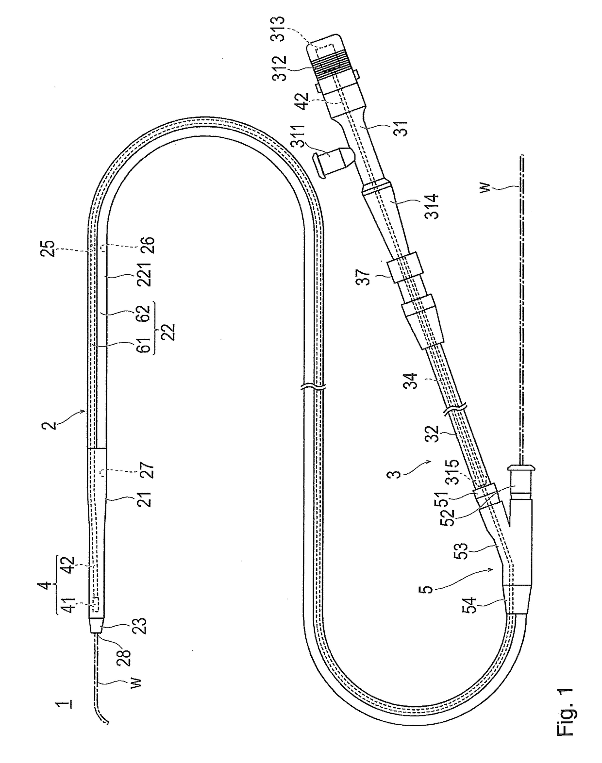
[0031]As illustrated in FIGS. 1 to 4, a medical device 1 is an ultrasound catheter that accommodates an imaging core 4 for performing ultrasound diagnosis and is configured to be inserted into a body lumen. The medical device 1 is connected to an external drive device 7 (refer to FIG. 8) that holds the medical device 1 and drives the imaging core 4, and the medical device is mainly used for performing diagnosis in a blood vessel. In this specification, a side, on which insertion into a lumen of a living body is performed, is referred to as a “distal end” or a “distal side”, and a hand side, on which an operation is performed, is referred to as ...


PUM

PropertyMeasurementUnit
angleaaaaaaaaaa
angleaaaaaaaaaa
angleaaaaaaaaaa

Abstract

A medical device having an imaging function includes a shaft main body portion having an image acquiring lumen and a guide wire lumen extending from a distal side to a proximal side of the shaft main body portion. A proximal portion of the shaft main body includes a first shaft proximal portion in which the image acquiring lumen is disposed, and a second shaft proximal portion in which the guide wire lumen is disposed, and which are bifurcated. A shaft distal portion has a common lumen in which the image acquiring lumen and the guide wire lumen converge, a first hub portion is interlocked with the first shaft proximal portion, a second hub portion is interlocked with the second shaft proximal portion, and a hub casing collectively covers the first shaft proximal portion, the second shaft proximal portion, the first hub portion and the second hub portion.

Description

CROSS-REFERENCES TO RELATED APPLICATIONS[0001]This application is a continuation of International Application No. PCT / JP2016 / 050139 filed on Jan. 5, 2016, and claims priority to Japanese Application No. 2015-001317 filed on Jan. 7, 2015, the entire content of both of which is incorporated herein by reference.TECHNICAL FIELD[0002]The present invention generally relates to a medical device insertable into a body lumen and configured to acquire image information.BACKGROUND ART[0003]When a target lesion in a lumen of a blood vessel, a vessel, and the like, is examined, an ultrasound catheter that transmits and receives ultrasound waves to and from the target lesion is used. The ultrasound catheter includes an imaging core that is provided with a transducer unit for transmitting and receiving the ultrasound waves and a drive shaft that causes the transducer unit to rotate, and a shaft portion in which the imaging core is internally installed and which is inserted in the lumen. The imagin...

Claims


Application Information

Patent Timeline
Patent Type & Authority Applications(United States)
IPC IPC(8): A61B8/12A61B8/00B29C65/00B29C65/56B29C65/02A61B8/13A61M25/00A61B8/08A61M25/09B29C47/00B29L31/00
CPCA61B8/12A61B8/13A61B8/481A61B8/445A61M25/0009A61M25/0097B29L2031/753A61M25/09041B29C47/0057B29C65/02B29C65/56B29C66/5227A61M2205/584A61M25/0041A61B1/00135A61B1/00154A61B8/0891A61B8/4461A61B5/0066B29C48/0018
Inventor YAMASHITA, YASUNORI
Owner TERUMO KK
Why Eureka
Try Eureka