Supercharge Your Innovation With Domain-Expert AI Agents!

Supporting member for implanting into vertebra and implanting system and method using the same

a technology of supporting members and vertebrae, which is applied in the field of supporting members for implanting into vertebrae and implanting system and method using the same, can solve the problems of osteoporosis patients being likely to lose so much bone tissue, affecting physical ability, and causing vertebral compression fractures

Active Publication Date: 2017-10-26
NAT TAIWAN UNIV HOSPITAL JINSHAN BRANCH
View PDF1 Cites 0 Cited by
  • Summary
  • Abstract
  • Description
  • Claims
  • Application Information

AI Technical Summary

Benefits of technology

The present invention provides a method for expanding the vertebral column from caudal (lower) to cranial (upper) using supporting members. This helps to increase the size of the spine.

Problems solved by technology

People diagnosed with osteoporosis are likely to lose so much bone tissue that they end up with a vertebral compression fracture.
However, osteoporosis patients in convalescence are predisposed to back pain and compression neuropathy and are to the detriment of physical ability; as a result, they become bedridden and even suffer from complications, such as bedsores, pneumonia, and urinary tract infections.
Sometimes osteoporosis-induced vertebral compression fractures do not heal, and the unhealed fractures are accompanied by persistent pain, leading to spinal instability and even lordosis, kyphosis, scoliosis, and deformation of vertebrae; eventually, adjacent vertebrae undergo vertebral compression fractures multiplied by a domino effect.
However, screws driven into osteoporosis patients' vertebrae are likely to loosen.
To solve this problem, more screws are driven into more vertebrae of an osteoporosis patient than a non-osteoporosis patient; as a result, prolonged surgery and massive bleeding lead to more complications, such as cardiopulmonary failure and infections.
Nonetheless, minimally invasive percutaneous vertebroplasty cannot correct a deformed vertebra.
However, when the required filler is too large, it is likely to injure peripheral nerves while passing through the pedicle.
But if the implanted filler is too small, it cannot support the vertebra.

Method used


Image

  • Supporting member for implanting into vertebra and implanting system and method using the same
  • Supporting member for implanting into vertebra and implanting system and method using the same
  • Supporting member for implanting into vertebra and implanting system and method using the same

Examples


Embodiment Construction

[0054]Unless otherwise defined herein, every technical or scientific term used herein has the same meaning as generally understood by persons skilled in the art pertaining to the present invention.

[0055]Unless otherwise specified herein, the words “a” and “an” used herein mean “at least one.”

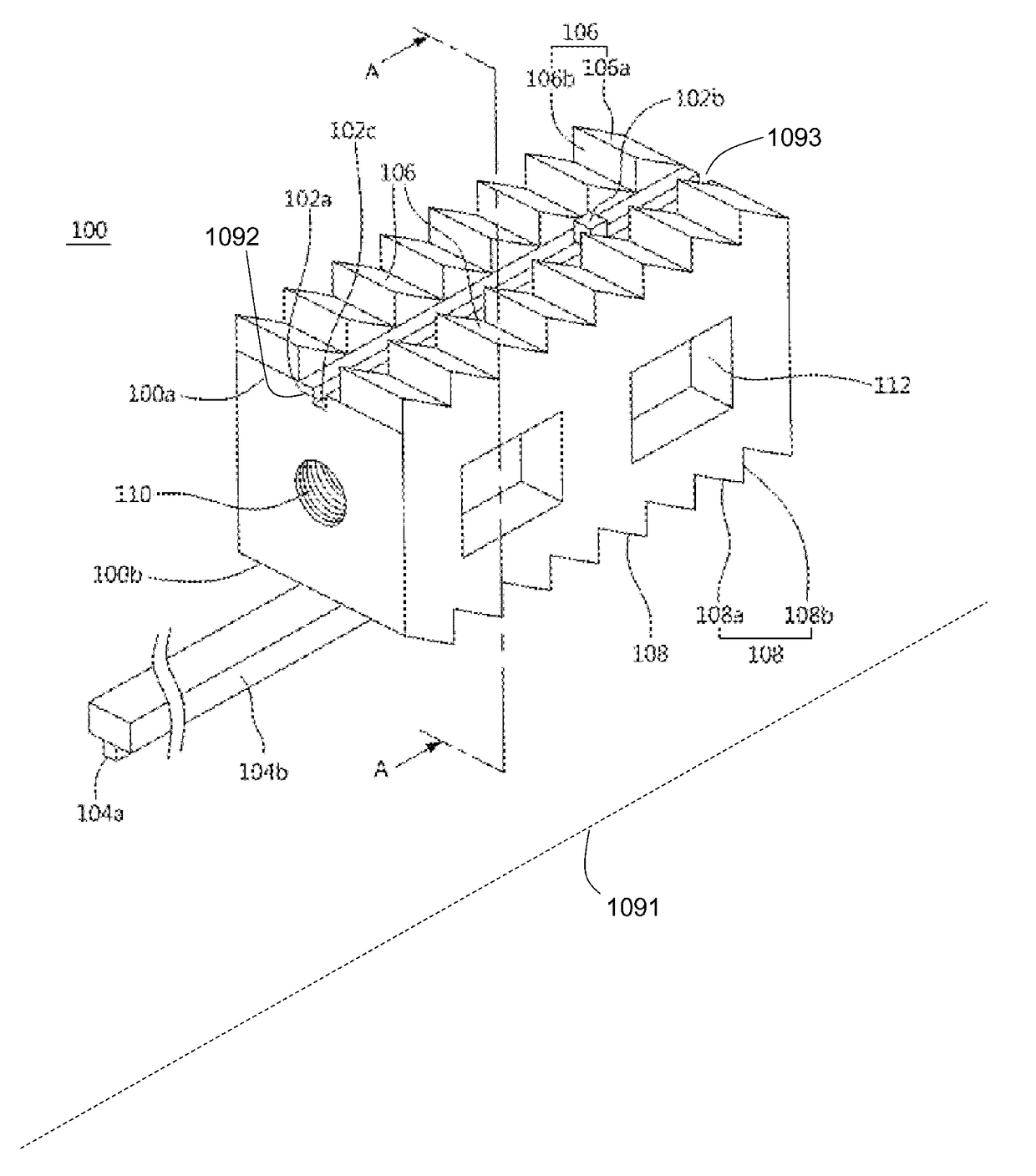
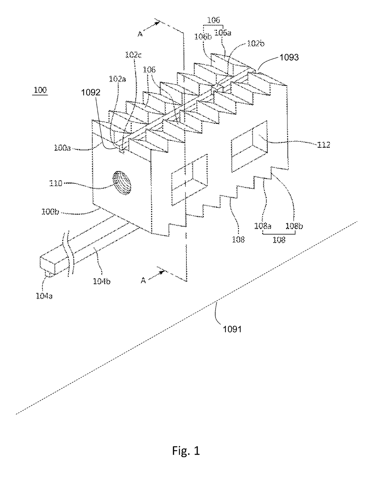
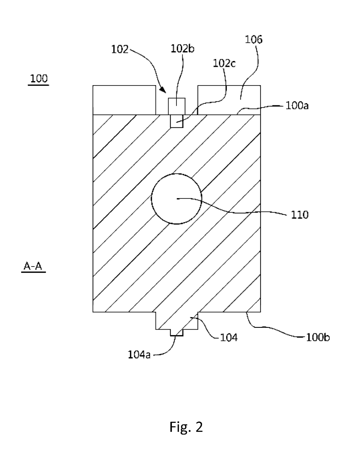
[0056]Referring to FIG. 1 and FIG. 2, there are shown a perspective view and a cross-sectional view of a supporting member for implanting into a vertebra according to the present invention. FIG. 2 is a cross-sectional view taken along line AA′ of FIG. 1. A supporting member 100 comprises an upper surface 100a and a lower surface 100b. Specifically, an upper surface 100a is parallel to a lower surface 100b. A first guide portion 102 is, for example, a recess formed on the upper surface 100a. A first guide portion 102 comprises a first proximal end 1092 extending to a first distal end 1093 along a first axis 1091. A second guide portion 104 is, for example, a rib formed on the lower surface 100b a...


PUM


Abstract

The present invention provides a supporting member for implanting into a vertebra of a subject, including: a hollow body including an upper surface and a lower surface opposite the upper surface; a first guiding part formed on the upper surface; a second guiding part corresponding to the first guiding part and formed on the lower surface; a first engaging part formed on the upper surface; and a second engaging part corresponding to the first engaging part and formed on the lower surface; wherein the second guiding part extends out an extending part from a side of the hollow body, and the extending part is configured to be slidably coupled to a first guiding part of another supporting member sliding to the lower surface of the supporting member, as a result two supporting members are slidably coupled to each other and engaged to each other. According to the invention, one single supporting member can be implanted into a vertebra of a subject, or two or more supporting members can be in sequence introduced into a vertebra of a subject and combined together therein.

Description

RELATED APPLICATIONS[0001]This application claims the benefit of Taiwanese Patent Application No. 105205769, filed on Apr. 22, 2016, the entire content of which is incorporated herein by reference.FIELD OF THE INVENTION[0002]The present invention relates to a supporting member for implanting into a vertebra, more particularly to multiple supporting members combinable in a vertebra. The present invention also relates to an intra-vertebral implanting system and method using the one or more supporting members.BACKGROUND OF THE INVENTION[0003]People diagnosed with osteoporosis are likely to lose so much bone tissue that they end up with a vertebral compression fracture. Most vertebral compression fractures heal in months. However, osteoporosis patients in convalescence are predisposed to back pain and compression neuropathy and are to the detriment of physical ability; as a result, they become bedridden and even suffer from complications, such as bedsores, pneumonia, and urinary tract i...

Claims


Application Information

Patent Timeline
Patent Type & Authority Applications(United States)
IPC IPC(8): A61F2/44A61F2/46A61F2/30
CPCA61F2/442A61F2/30771A61F2/4611A61F2/4601A61F2002/30604A61F2002/30593A61F2002/30377A61F2002/4435A61F2002/30904A61B17/7094A61F2/4455A61F2002/30367
Inventor HSIEH, JUI-YANG
Owner NAT TAIWAN UNIV HOSPITAL JINSHAN BRANCH
Features
  • R&D
  • Intellectual Property
  • Life Sciences
  • Materials
  • Tech Scout
  • Unparalleled Data Quality
  • Higher Quality Content
  • 60% Fewer Hallucinations
Learn More