Electric hinge

a technology of hinges and hinge plates, applied in the direction of pin hinges, door/window fittings, constructions, etc., can solve the problems of reducing the efficiency of the manufacturing and installation process, affecting the quality of the hinge plate, so as to reduce the process cycle and overall manufacturing time, shorten the drilling time, and improve the effect of manufacturing and installation efficiency

Active Publication Date: 2017-10-26
CORBIN RUSSWIN
View PDF6 Cites 11 Cited by
  • Summary
  • Abstract
  • Description
  • Claims
  • Application Information

AI Technical Summary

Benefits of technology

[0003]Accordingly, the need exists to drill shorter passageways for running wiring for electric power or information, which would shorten the drilling time for the hinges, and improve manufacturing and installation efficiency as well as reduce process cycles and overall manufacturing time required.

Problems solved by technology

In addition, the removal of scrap chips from the drilling process through the entire width of the hinge plate also tends to be more difficult, taking extra time in the drilling procedure.
Additionally, fishing the wires through the wiring hole becomes more difficult through longer wiring holes, especially considering that four wires may be required in each hole.
Wires which include twisted pairs or twisted wire groups may make the running of the wires even more arduous.

Method used


Image

  • Electric hinge
  • Electric hinge
  • Electric hinge

Examples


Embodiment Construction

)

[0033]In describing the embodiments of the present invention, reference will be made herein to FIGS. 2-13 of the drawings in which like numerals refer to like features of the invention.

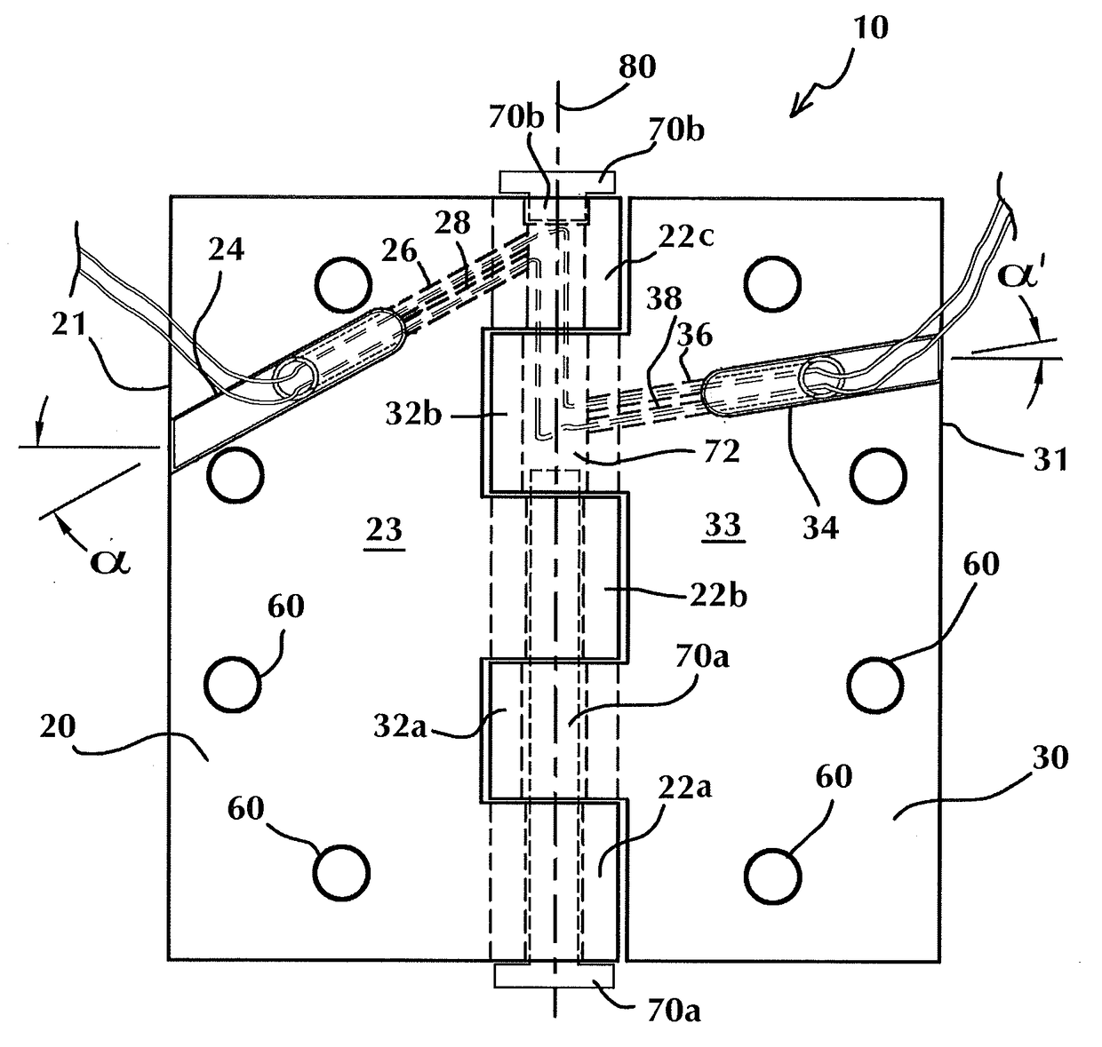
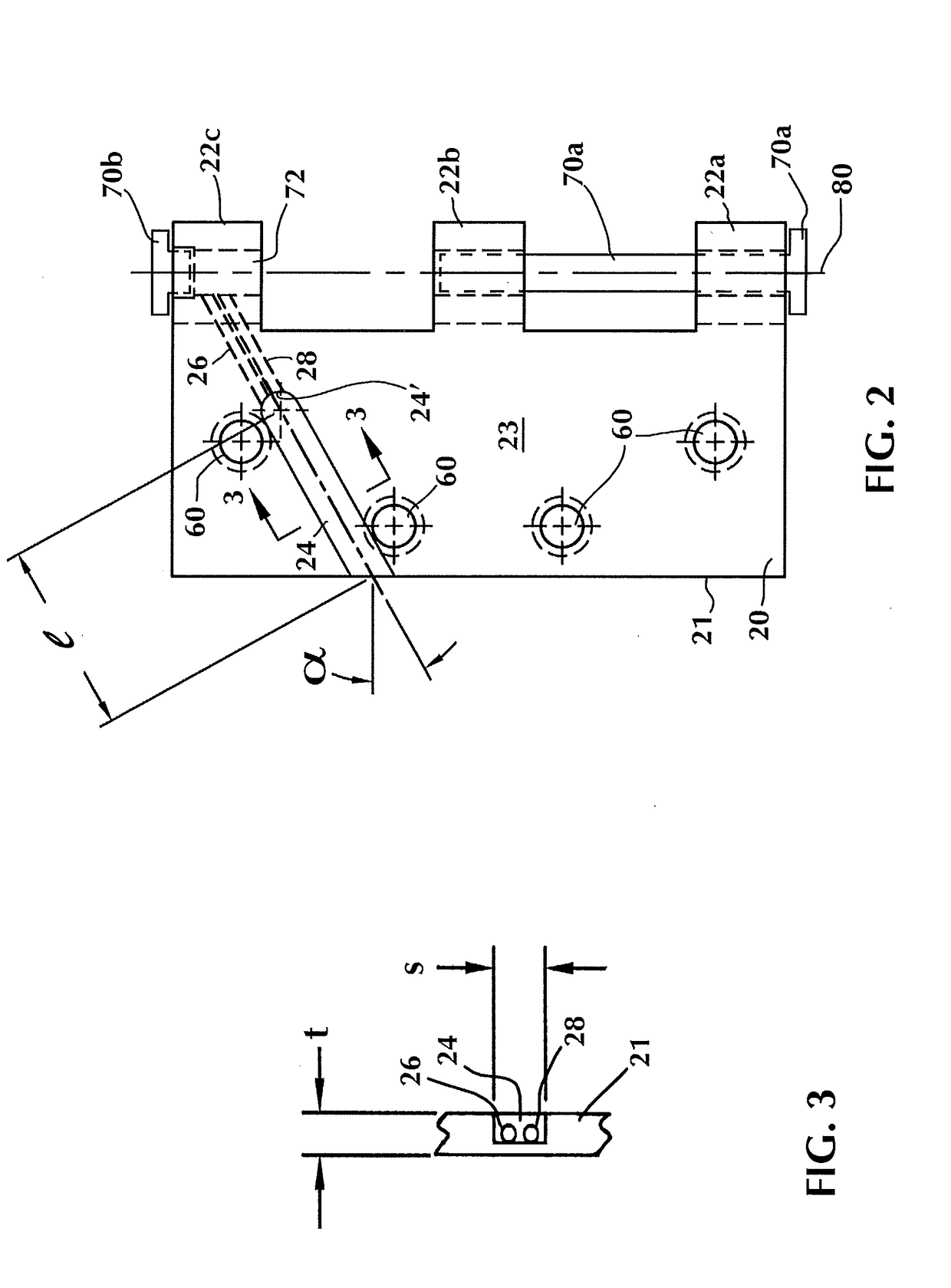
[0034]The present invention provides both an electric hinge and a method for making the electric hinge. As shown in FIGS. 2-4 and 12, the pin and barrel or knuckle-type electric hinge 10 includes hinge leaf or plate 20, 30, having mounting holes 60 for fastening the hinge plate with the surface shown placed flush against the door or door frame. Hinge plate 20 has door- or frame-contacting surface 23 and includes three knuckles 22a, 22b, 22c on one edge for receiving one or more hinge pins 70a, 70 in one or more of the knuckles, and distal edge 21 opposite the knuckles. Hinge plate 30 has door- or frame-contacting surface 33 and includes two knuckles 32a, 32b on one edge sized to be received between and mating with the knuckles of hinge plate 20, and distal edge 31 opposite the knuckles. Knuckles 22a,...


PUM


Abstract

A method for making an electric hinge comprising providing first and second hinge plates, each hinge plate having at least one knuckle and forming in each hinge plate an open slot extending from an edge distal from the knuckle and terminating at a mid-portion of the hinge plate to the knuckle. The open slot depth is less than the thickness of the hinge plate. The method includes drilling a hole from the terminus of each open slot to the knuckle of the hinge plate and passing a wire through the hole from the terminus of the open slot to the knuckle in the first hinge plate and from the knuckle of the second hinge plate to the corresponding terminus of the second hinge plate. The method includes mating the first and second hinge plates by inserting a hinge pin through the knuckle of each hinge plates to form the electric hinge.

Description

BACKGROUND OF THE INVENTION1. Field of the Invention[0001]This invention relates to door mounting hardware and in particular to a door hinge capable of facilitating electrical connection with hardware such as electric locks carried in the door.2. Description of Related Art[0002]The term “electric hinge” as used in the door hardware industry refers to a door, panel or window hinge which carries wires to transfer electrical power and / or information between the surrounding wall or frame and hardware carried on the door, such as electric locks, closers, openers and sensors. An electric hinge 20′ according to the prior art as shown in FIG. 1 installs wires through small diameter holes 26′, 28′ that have been drilled within the thickness of and through the entire width of the hinge leaf or plate. The wiring hole ends at a hinge knuckle 22′, typically at an end knuckle of one of the pair of hinge plates, so that the wires can pass through the pin hole in a knuckle on one plate of the hinge...

Claims


Application Information

Patent Timeline
Patent Type & Authority Applications(United States)
IPC IPC(8): E05D11/00E05D3/02E05D5/04
CPCE05D11/0081E05D3/02E05D11/0054E05Y2201/11E05Y2900/132E05Y2400/654E05D5/04
Inventor SOLOSKI, EDWARDNAPLES, THOMASGRANT, KENNETH
Owner CORBIN RUSSWIN
Why Eureka
Try Eureka