Rupture Disc Valve Device

a technology of rupture disc and valve device, which is applied in the direction of valve housing, pressure relieving device on sealing face, functional valve type, etc., can solve the problems of undetectable variance in burst pressure, leakage, and unfavorable burst pressure, and achieve the effect of reducing forces and increasing back pressur

Inactive Publication Date: 2017-10-26
OKLAHOMA SAFETY EQUIP
View PDF12 Cites 12 Cited by
  • Summary
  • Abstract
  • Description
  • Claims
  • Application Information

AI Technical Summary

Benefits of technology

[0007]Accordingly, the rupture disc valve device herein has a valve body with a solid outer surface such that there are no potential leakage paths to the radial outer periphery of the device. To this end, the welds between the disc and the valve body and the components of the value body are radially inward from the radially outer surface of the valve body. In a preferred form, the rupture disc has its frangible dome wall portion disposed in a linear throughbore of the valve body in a reverse-acting orientation so that the convex side of the dome wall portion of the disc is oriented toward the inlet of the valve body. In this manner, the pressure of the process media generates compressive forces in the radially inward weld joint which contributes to the sealing effect achieved thereby. This also allows the weld joint between the rupture disc and the valve body to be less robust while still achieving a proper seal therebetween.
[0017]In another form, the valve device can include a valve body and two pivotable support members pivotably coupled to the valve body. The support members include an upstream, primary member and a downstream, secondary member that pivot between a first position in a stacked relation extending transverse to a flow path through the valve assembly and a second position extending downstream generally along the flow path. In the first position, the primary support member extends along and braces the rupture disc blocking flow through the valve assembly and the secondary support member extends along and braces the primary support member. The secondary support member is retained or kept in the first position by an actuator having a release. Configuring the two support members to distribute the forces created by bracing the rupture disc advantageously reduces the forces on the release as compared to a single support member.

Problems solved by technology

In one aspect, it has been found that the peripheral edge joint weld of the two-piece holder rupture disc assembly can create an undesired variance in the burst pressures of the rupture discs due to the radially directed energy along the rupture disc that is generated during the welding process.
Moreover, since the weld is exposed on the outer peripheral surface of the rupture disc assembly, any defects in the weld can create leakage issues.
Depending on the metallurgical properties of rupture disc, such radially directed heat can create unwanted variances in the desired burst pressures of the rupture disc.
Furthermore, because of the previously described ability to create less robust or lower strength weld joints with the reverse-acting arrangement of the preferred rupture disc valve device herein, this further contributes to the lowering of the heat energy needed during the welding process which, in turn, contributes to maintaining desired burst pressures of the rupture disc.
This problem of creating unwanted variances in the desired burst pressures due to radially directed heat along the rupture disc such as generated when creating the weld joint at the outer periphery of the valve body is particularly problematic with rupture discs that have low burst pressure requirements.
However, to achieve the full range of pressures including low burst pressure requirements, thinner rupture disc material is required which is more likely to be affected with radially directed welding such as used for generating the peripheral edge joint weld in the prior rupture disc assembly.

Method used


Image

  • Rupture Disc Valve Device
  • Rupture Disc Valve Device
  • Rupture Disc Valve Device

Examples


Embodiment Construction

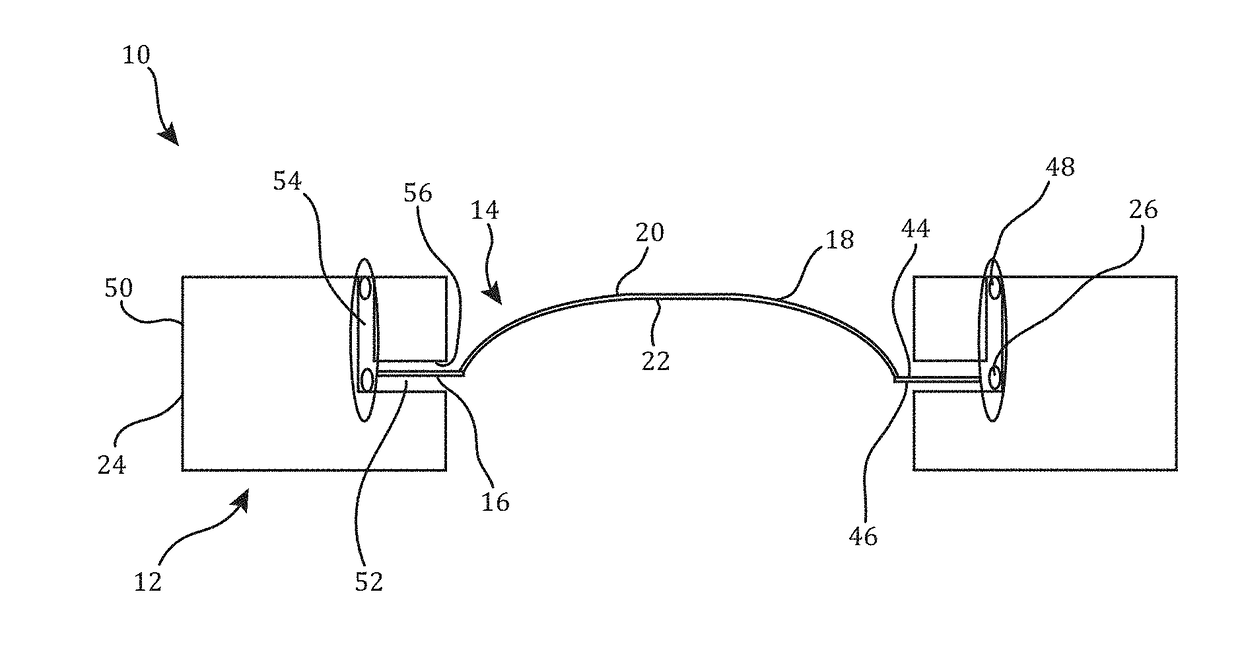
[0050]FIG. 1 shows a rupture disc valve device 10 having a valve body 12 and a rupture disc 14 secured thereto. The rupture disc 14 has a flat, outer ring portion 16 and a central, frangible dome wall portion 18 at the radial center of the rupture disc 14. The central dome wall portion 18 of the rupture disc 14 has a convex surface 20 and a concave surface 22 which can have a constant thickness therebetween. The frangible dome wall portion 18 is configured to rupture at a predetermined burst pressure depending on several factors relating to its configuration including the thickness of the dome wall portion 18 and the amount, type and configuration of any scoring provided in either or both of the convex and concave surfaces 20, 22 thereof.

[0051]As can be seen, the valve body 12 has a radially outer surface 24 and the rupture disc 14 is secured to the valve body 12 via a weld joint 26 that is spaced radially inward from the valve body outer surface 24 so as not to be exposed thereat. ...


PUM


Abstract

A rupture disc valve device as provided herein is configured to selectively release a pressurized material. In some embodiments, the rupture disc has a burst pressure rating less than a pressure of the pressurized material. The valve device selectively braces the rupture disc until release of the pressurized material is desired. To release the pressurized material, the valve device is configured to remove or adjust the bracing support to the rupture disc, allowing the pressurized material to burst the rupture disc.

Description

CROSS-REFERENCE TO RELATED APPLICATIONS[0001]This application claims the benefit of U.S. Application No. 62 / 380,003, filed Aug. 26, 2016, and U.S. Application No. 62 / 326,598, filed Apr. 22, 2016, which are both incorporated by reference herein in their entireties.FIELD OF THE INVENTION[0002]The present invention relates to a rupture disc valve device and its assembly and, more particularly, to a sealed rupture disc valve device, a welding method therefor, and rupture disc valve assemblies for a fire suppressant system.BACKGROUND OF THE INVENTION[0003]Rupture discs are used in a variety of chemical process and manufacturing applications. In these applications, hazardous, caustic and corrosive media may be used or produced. For these systems, rupture disc valve assemblies that include a multi-piece holder are known where the rupture disc is held in place under the tension of a bolted flange. However, when exposed to harsh media, corrosion and disruption of the disc can cause unwanted ...

Claims


Application Information

Patent Timeline
Patent Type & Authority Applications(United States)
IPC IPC(8): F16K17/16F16K27/02A62C35/68F16K39/02F16K27/10A62C35/02
CPCF16K17/16F16K27/02A62C35/023F16K39/02A62C35/68F16K27/102A62C13/70F16K17/10F16K17/1606F16K17/168A62C37/46F16K15/1821
Inventor WILSON, ALAN T.FRANKS, HUNTERHENTZEN, BRANDONKMITTA, MICHAELBLACKMON, MARK RANDALLEVANS, ROBERTJOHNSON, JERROD PHILLIPULRICH, CARL RYANGOODYEAR, ERIC ALANSTOCKSTILL, DOYLE G.
Owner OKLAHOMA SAFETY EQUIP
Why Eureka
Try Eureka