A valve arrangement, a method for identifying an underground valve of a valve arrangement and use of a use of valve arrangement

a technology of underground valves and valve arrangements, applied in the field of valve arrangements, can solve the problems of difficult to subsequently identify the specific valve type, information may be lost, and the use of wireless transmission is vulnerable, and achieves the effect of simple and inexpensive means

Active Publication Date: 2017-10-26
AVK HLDG AS
View PDF9 Cites 4 Cited by
  • Summary
  • Abstract
  • Description
  • Claims
  • Application Information

AI Technical Summary

Benefits of technology

[0008]Providing the extension device with dedicated connection means extending substantially the length of the extension device is advantageous in that such physical connection means are less vulnerable—thus enabling a more durable way of identifying the valve.
[0068]It is advantageous to use a valve arrangement according to the present invention for ground surface control of a fluid flow in underground pipe means in that the identity of the valve hereby easily can be checked even may years after installation.

Problems solved by technology

However, these valves may be in use for several decades and even if the exact type of valve used at a specific location in the network was properly documented at installation, this information may get lost over time e.g. due to mergers, fire, replacement of defect valves or other.
And since the valves typically are located on the buried pipes it is often difficult to subsequently identify the specific valve type without having to unearth it.
However, such wireless transmission is vulnerable particularly in light of the relatively long lifespan of a typical valve.
Furthermore, such wireless communication is only one-way.

Method used


Image

  • A valve arrangement, a method for identifying an underground valve of a valve arrangement and use of a use of valve arrangement
  • A valve arrangement, a method for identifying an underground valve of a valve arrangement and use of a use of valve arrangement
  • A valve arrangement, a method for identifying an underground valve of a valve arrangement and use of a use of valve arrangement

Examples


Embodiment Construction

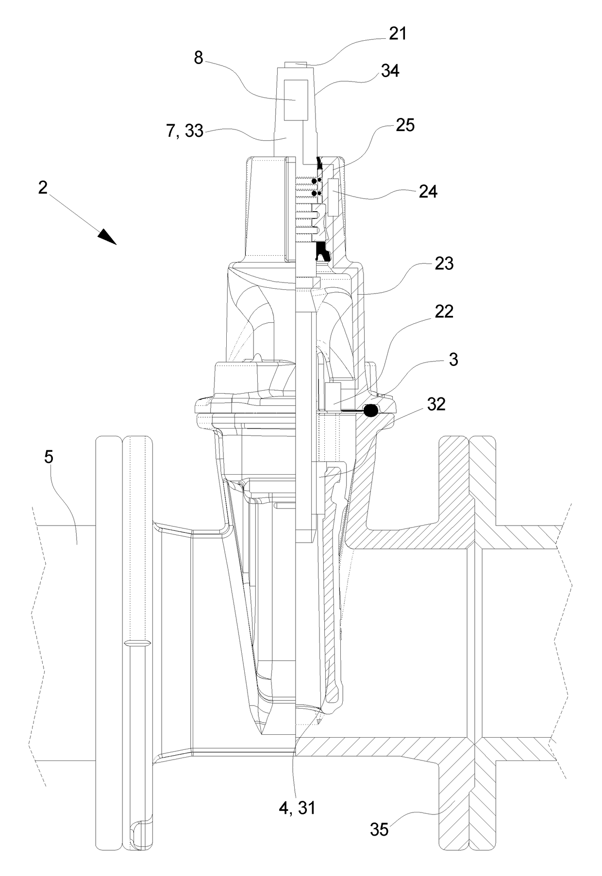
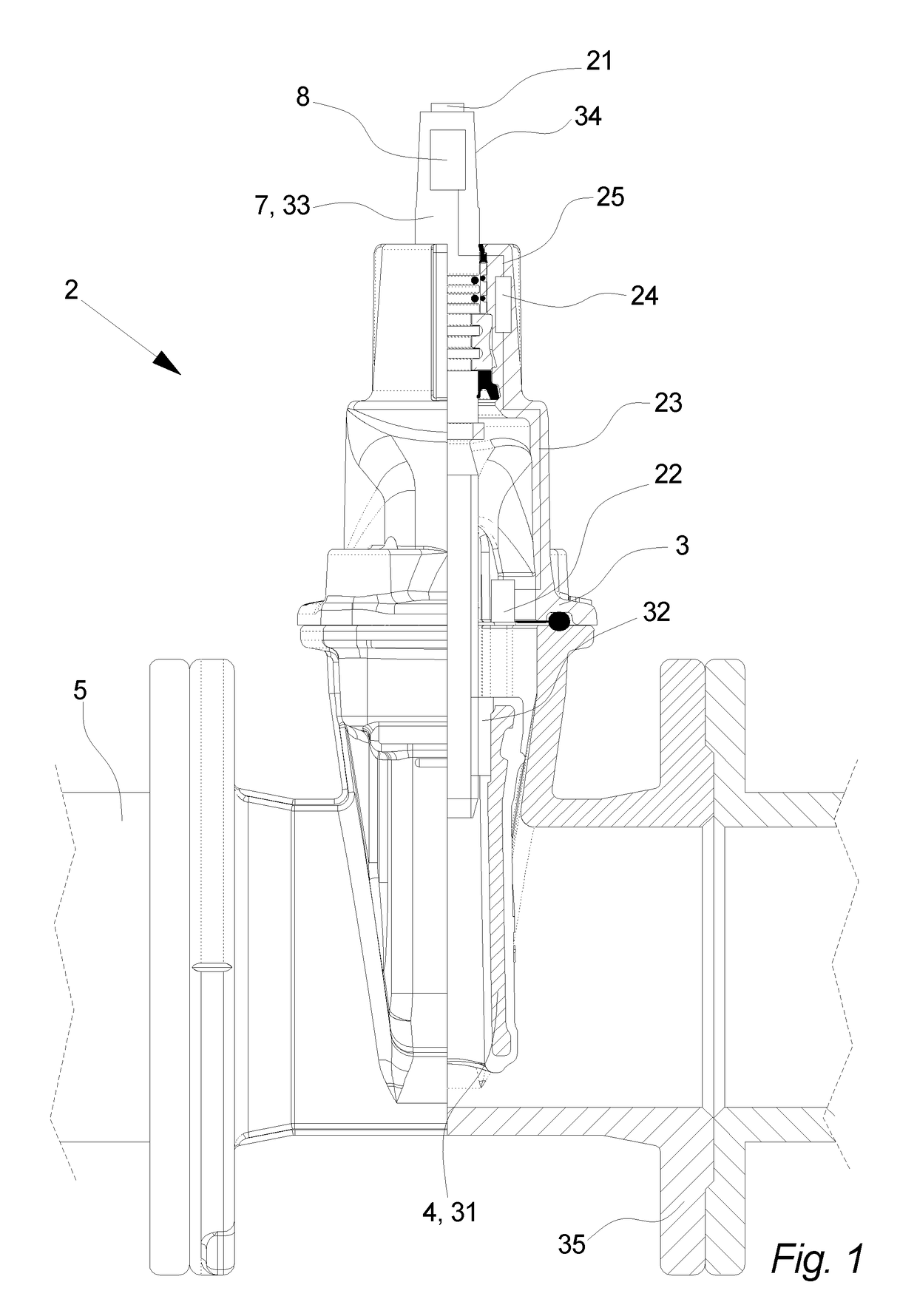
[0074]FIG. 1 illustrates a partial cross section through the middle of a valve 2, as seen from the side.

[0075]In this embodiment the valve 2 comprises fluid control means 4 in the form of a vertically displaceable wedge 31 comprising a wedge nut 32. The valve 2 also comprises an operating device 7 in the form of a substantially centrally arranged spindle 33 engaging the wedge nut 32 at one end and at the other end is arranged a valve engaging device 34 enabling that the operating device 7 may be mechanical manipulated—i.e. in this case rotated—so that the nut 32 and thereby the wedge 31 is raised or lowered to open or close the valve 2 or at least control the clearance through the valve 2 to control the flow of a fluid through the valve 2.

[0076]However, in another embodiment the valve 2 could be a butterfly valve, a check valve, a ball valve or another type of valve 2 suited for controlling a flow of fluid through pipe means 5 to which the valve 2 is connected—i.e. in another embodi...


PUM


Abstract

Disclosed is a valve arrangement for underground control of a fluid flow and an associated method, the arrangement including a valve having a valve housing containing fluid control means for controlling a flow of fluid through pipe means arranged below the surface of the ground, where the fluid control means is actuated by means of mechanical manipulation of an operating device of the valve and the operating device is coupled to the fluid control means, the valve having valve identification means including data regarding the specific valve type, where the valve arrangement further includes an extension device including an extension device housing surrounding an extension rod, where the extension rod is rotatably supported by the extension device housing, where the extension rod is mechanically coupled to the operating device to enable the mechanical manipulation being performed at the ground surface, and the extension device further includes dedicated connection means extending between a valve end and a ground surface end of the extension device, and the valve end is arranged at the valve housing and the ground surface end is arranged at the opposite end of the extension device, where the dedicated connection means enable that the data regarding the specific valve type may be communicated to the ground surface.

Description

TECHNICAL FIELD[0001]The invention relates to a valve arrangement for underground control of a fluid flow.[0002]The invention also relates to a method for identifying an underground valve of a valve arrangement comprising an extension device being connected to the valve and use of a valve arrangement.BACKGROUND[0003]Underground pipe networks are used when distributing e.g. utility water, waste water, central heating, natural gas or other fluids over large areas. To enable that sections of the buried pipe network can be isolated e.g. during repair or fault localisation or simply to control the distribution in the network it is known to provide valves at strategic nodes and other locations in the pipe network.[0004]However, these valves may be in use for several decades and even if the exact type of valve used at a specific location in the network was properly documented at installation, this information may get lost over time e.g. due to mergers, fire, replacement of defect valves or...

Claims


Application Information

Patent Timeline
Patent Type & Authority Applications(United States)
IPC IPC(8): F16K37/00E03B9/02E03B7/07
CPCF16K37/0041E03B7/07E03B9/02Y10T137/6995Y10T137/6991Y10T137/701
Inventor FREUDENDAHL, ERLING ARNUM
Owner AVK HLDG AS
Why Eureka
Try Eureka