Systems and methods for pipeline device propulsion

Inactive Publication Date: 2017-10-26
ELWHA LLC
View PDF1 Cites 2 Cited by
  • Summary
  • Abstract
  • Description
  • Claims
  • Application Information

AI Technical Summary

Benefits of technology

The present patent provides a method and device for sealing a leak in a pipeline used for transporting fluid. The device includes a sealing device and an inflatable bag that can be inflated by a gas generator to seal the leak and prevent the fluid from leaking out of the pipe. The device is designed to move through the pipeline to the location of the leak and to inflate the sealing device to cover the leak and prevent fluid loss. This technology allows for quick and effective repair of leaks in pipelines, reducing fluid loss and downtime.

Problems solved by technology

However, the pipeline may develop a leak or rupture through which the fluid goods may escape, resulting in a loss of goods and potentially causing further damage to the pipeline if the rupture or leak is not patched or sealed within a reasonable time.
However, the fluid goods within this particular segment, which may be a stretch of pipeline over a long distance, may be lost through the leak before the leak can be patched or sealed.
Also, the closed block valves may prevent fluid from being transported through the pipeline until the leak is sealed, perhaps blocking the supply of the fluid goods to one or more locations for a prolonged period of time.

Method used


Image

  • Systems and methods for pipeline device propulsion
  • Systems and methods for pipeline device propulsion
  • Systems and methods for pipeline device propulsion

Examples


Embodiment Construction

[0027]In the following detailed description, reference is made to the accompanying drawings, which form a part hereof. In the drawings, similar symbols typically identify similar components, unless context dictates otherwise. The illustrative embodiments described in the detailed description, drawings, and claims are not meant to be limiting. Other embodiments may be utilized, and other changes may be made, without departing from the spirit or scope of the subject matter presented here.

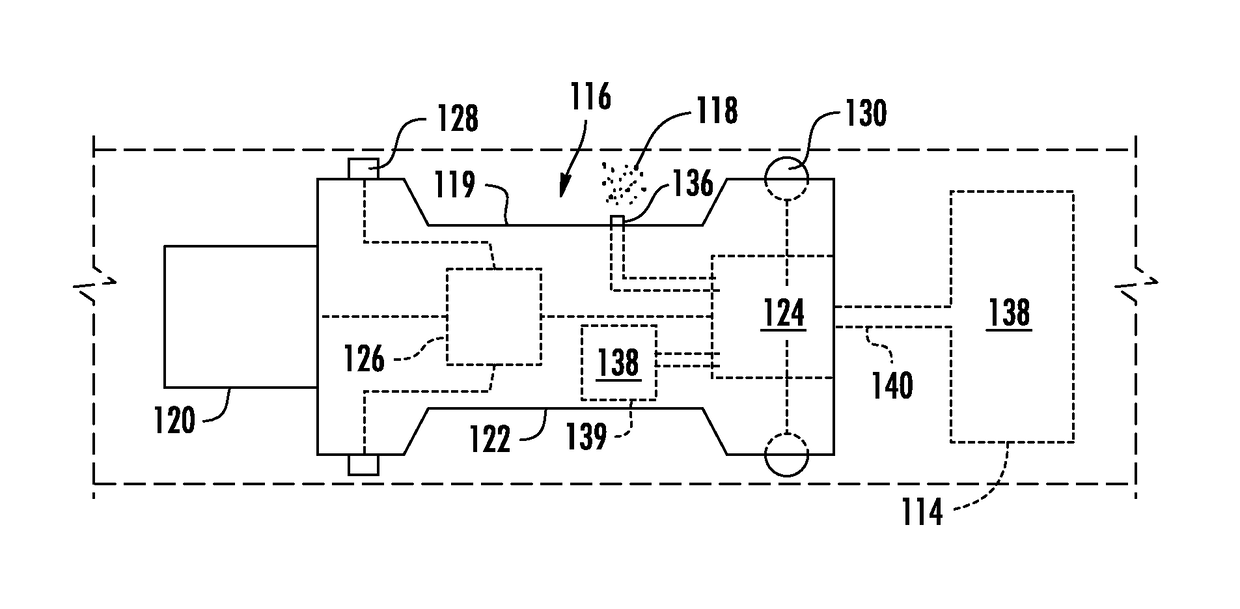
[0028]Referring generally to the figures, a leak sealing system is shown for sealing a leak within a fluid pipeline. The leak sealing system includes a sealing device configured to move to a leak location within the pipeline, deploying or inflating to seal a leak within the pipeline. The sealing device is sized and shaped such that fluid is able to flow past or through the sealing device when the sealing device is inflated, maintaining the transportation of fluid through the pipeline. The leak sealing...


PUM


Abstract

A method for sealing a leak in a pipeline used to transport fluid includes positioning a sealing device within the pipeline, moving the sealing device through the pipeline to a leak location, and internally generating an inflation pressure to inflate the sealing device to substantially cover a leak opening and limit release of the fluid from the pipeline.

Description

CROSS-REFERENCE TO RELATED PATENT APPLICATIONS[0001]The present application is a continuation of U.S. application Ser. No. 14 / 533,707, filed Nov. 5, 2014, which is a continuation-in-part of U.S. application Ser. No. 13 / 955,929, filed Jul. 31, 2013. Both applications are incorporated herein by reference in their entirety.BACKGROUND[0002]Pipelines are used to transport fuels and other fluid goods between one or more locations. For instance, pipeline transport is often the most economical way to transport large quantities of oil or natural gas over land. A pipeline for transporting fluid goods is constructed to resist ruptures or leaks within the pipeline. However, the pipeline may develop a leak or rupture through which the fluid goods may escape, resulting in a loss of goods and potentially causing further damage to the pipeline if the rupture or leak is not patched or sealed within a reasonable time.[0003]A fluid pipeline may include block valves or block valve stations positioned a...

Claims


Application Information

Patent Timeline
IPC IPC(8): F16L55/1645F16L55/165
CPCF16L55/1645F16L55/1654F16L55/32G01M3/246G01M3/2807G01M3/2823G01M3/38F16L55/1283
Inventor CHEATHAM, III, JESSE R.DUNCAN, WILLIAM D.GATES, WILLIAMHYDE, RODERICK A.ISHIKAWA, MURIEL Y.KARE, JORDIN T.MYHRVOLD, NATHAN P.PAN, TONY S.PETROSKI, ROBERT C.TEGREENE, CLARENCE T.WOOD, JR., LOWELL L.WOOD, VICTORIA Y.H.
Owner ELWHA LLC
Why Eureka
Try Eureka