Multi-Stage Reverse Osmosis Systems and Methods

a reverse osmosis system and reverse osmosis technology, applied in the nature of treatment water, waste water treatment from quaries, membranes, etc., can solve the problems of bringing a further undesirable environmental cost and high cost of water purification in reverse osmosis systems

Active Publication Date: 2017-11-09
MASSACHUSETTS INST OF TECH
View PDF5 Cites 2 Cited by
  • Summary
  • Abstract
  • Description
  • Claims
  • Application Information

AI Technical Summary

Benefits of technology

[0006]In accordance with another embodiment of the present disclosure, an improved method of operating a reverse osmosis separation system has at least first and second stages and is of a type wherein (i) each stage has at least one reverse osmosis membrane, (ii) each stage has a feed stream inlet for a feed stream, a permeate stream outlet for a permeate stream, and a concentrate stream outlet for a concentrate stream, (iii) the feed stream inlet of the second stage is coupled to the concentrate stream outlet of the first stage, (iv) the feed stream entering the first stage is pressurized to a first pressure and the feed stream entering the second stage is pressurized to a second pressure, (v) the second pressure is greater than the first pressure, and (vi) pressure exchangers associated with each of the first and second stages are configured to recover energy from the second stage concentrate stream. The improved method includes providing M reverse osmosis membranes in the first stage and N reverse osmosis membranes in the second stage, wherein M≧N, and configuring the first pressure and second pressure so that spatial variance in flux of the first stage permeate stream relative to flux of the second stage permeate stream is minimized.

Problems solved by technology

Water purified in reverse osmosis systems can be costly as compared to, for example, wastewater treatment or importation due the significant energy consumed in operation.
Further, the energy consumed in many cases takes the form of burning fossil fuels which brings a further undesirable environmental cost.

Method used


Image

  • Multi-Stage Reverse Osmosis Systems and Methods
  • Multi-Stage Reverse Osmosis Systems and Methods
  • Multi-Stage Reverse Osmosis Systems and Methods

Examples


Embodiment Construction

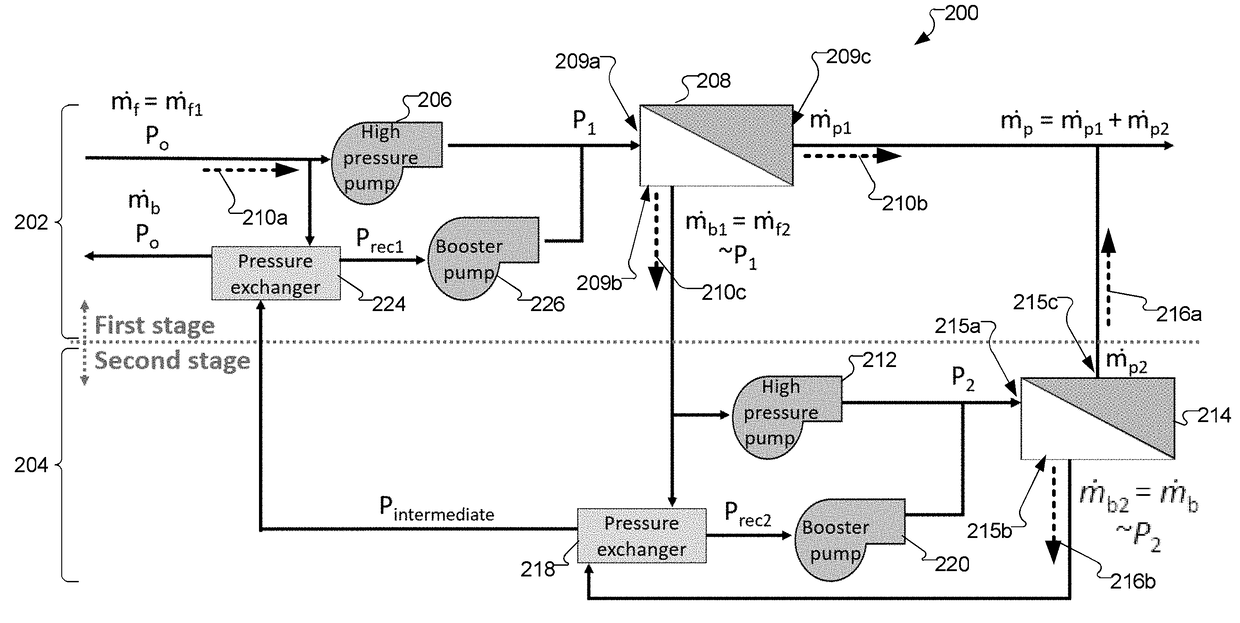
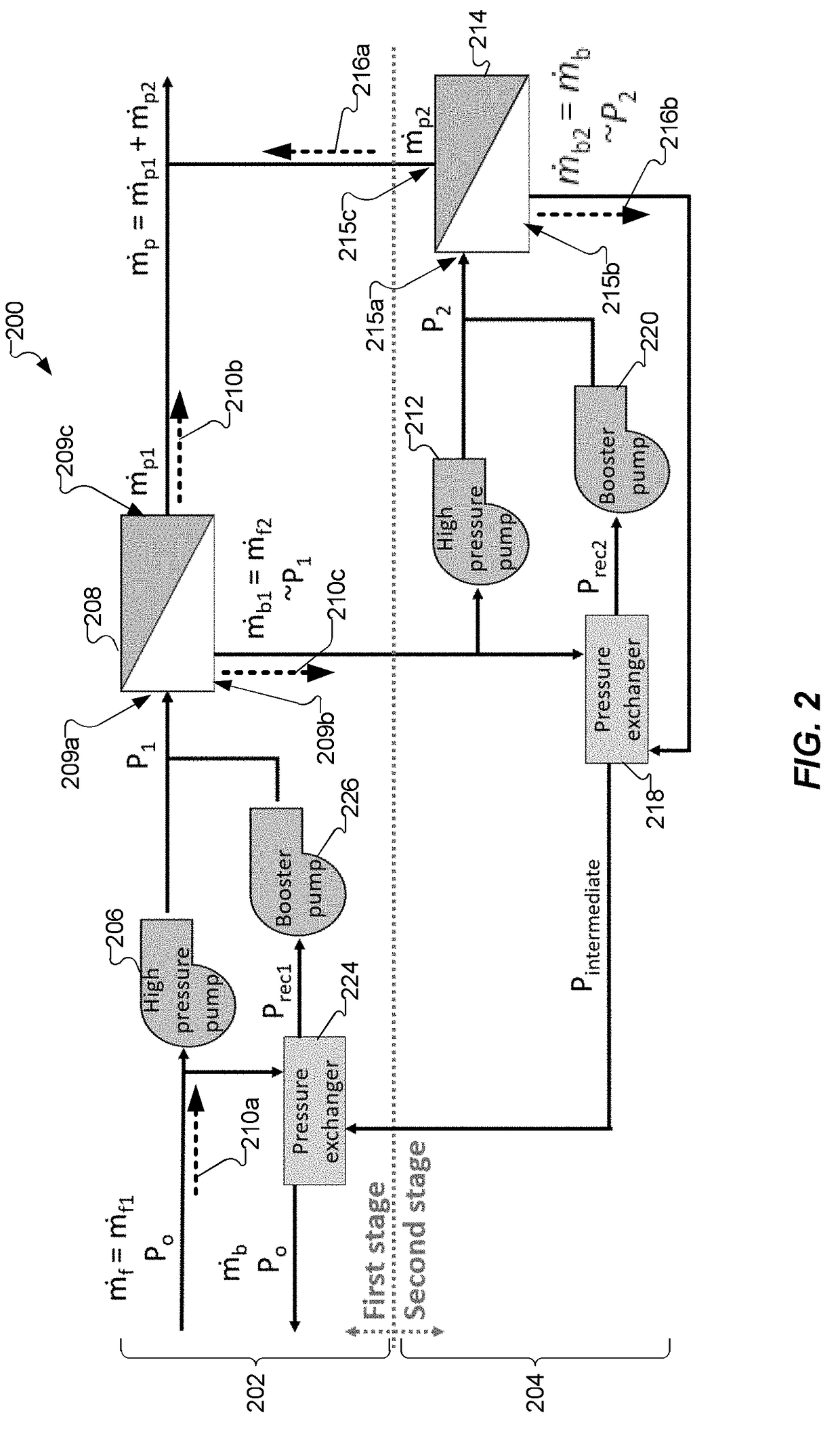
[0004]In accordance with one embodiment of the present disclosure, an improved reverse osmosis separation system includes at least first and second stages and is of a type wherein (i) each stage has at least one reverse osmosis membrane, (ii) each stage has a feed stream inlet for a feed stream, a permeate stream outlet for a permeate stream, and a concentrate stream outlet for a concentrate stream, (iii) the feed stream inlet of the second stage is coupled to the concentrate stream outlet of the first stage, (iv) the feed stream entering the first stage is pressurized to a first pressure and the feed stream entering the second stage is pressurized to a second pressure, (v) the second pressure is greater than the first pressure, and (vi) pressure exchangers associated with each of the first and second stages are configured to recover energy from the second stage concentrate stream. The improved reverse osmosis separation system includes M reverse osmosis membranes in the first stage...


PUM

PropertyMeasurementUnit
pressure exchanger efficiency ηPaaaaaaaaaa
solubilityaaaaaaaaaa
salinityaaaaaaaaaa

Abstract

Improved reverse osmosis (RO) systems include at least first and second stages wherein each stage has at least one RO membrane, each stage has a feed stream inlet, a permeate stream outlet, and a concentrate stream outlet, the feed stream inlet of the second stage is coupled to the concentrate stream outlet of the first stage, the second pressure is greater than the first pressure, and pressure exchangers associated with each of the first and second stages are configured to recover energy from the second stage concentrate stream. The systems include M reverse osmosis membranes in the first stage and N reverse osmosis membranes in the second stage, wherein M≧N. The first pressure and second pressure are configured so that spatial variance in flux of the first stage permeate stream relative to flux of the second stage permeate stream is minimized.

Description

CROSS-REFERENCE TO RELATED APPLICATION[0001]This patent application claims the benefit of U.S. Provisional Patent Application No. 62 / 331,606 filed May 4, 2016, the disclosure of which is incorporated by reference herein in its entirety.TECHNICAL FIELD[0002]The present invention relates to reverse osmosis systems and methods of operating same, and more particularly to multi-stage reverse osmosis systems and methods of operating same.BACKGROUND ART[0003]Water purified in reverse osmosis systems can be costly as compared to, for example, wastewater treatment or importation due the significant energy consumed in operation. Further, the energy consumed in many cases takes the form of burning fossil fuels which brings a further undesirable environmental cost. Benefits of increasing energy efficiency of reverse osmosis systems include greater adoption of these systems and a more effective use of natural resources.SUMMARY OF THE EMBODIMENTS[0004]In accordance with one embodiment of the pres...

Claims


Application Information

Patent Timeline
Patent Type & Authority Applications(United States)
IPC IPC(8): B01D61/02C02F1/44C02F101/12C02F103/08
CPCB01D61/022C02F1/441B01D2317/06C02F2101/12B01D2317/022C02F2103/08B01D61/025B01D63/12B01D2311/14C02F2103/10C02F2103/365C02F2301/08Y02A20/131B01D61/026
Inventor WEI, QUANTUM J.MCGOVERN, RONAN KILLIANLIENHARD, V, JOHN H.
Owner MASSACHUSETTS INST OF TECH
Why Eureka
Try Eureka