Printing assembly

Active Publication Date: 2017-11-09
KOENIG & BAUER AG
View PDF3 Cites 9 Cited by
  • Summary
  • Abstract
  • Description
  • Claims
  • Application Information

AI Technical Summary

Benefits of technology

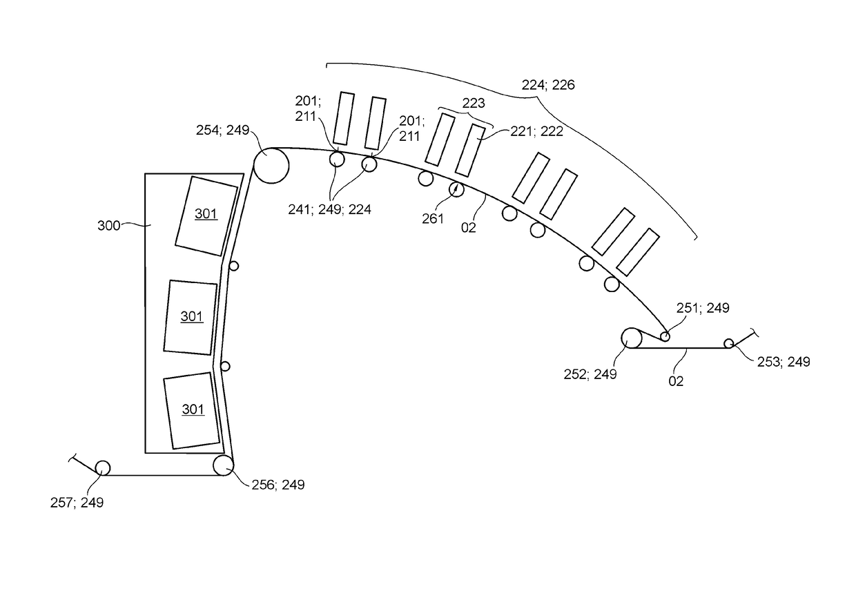
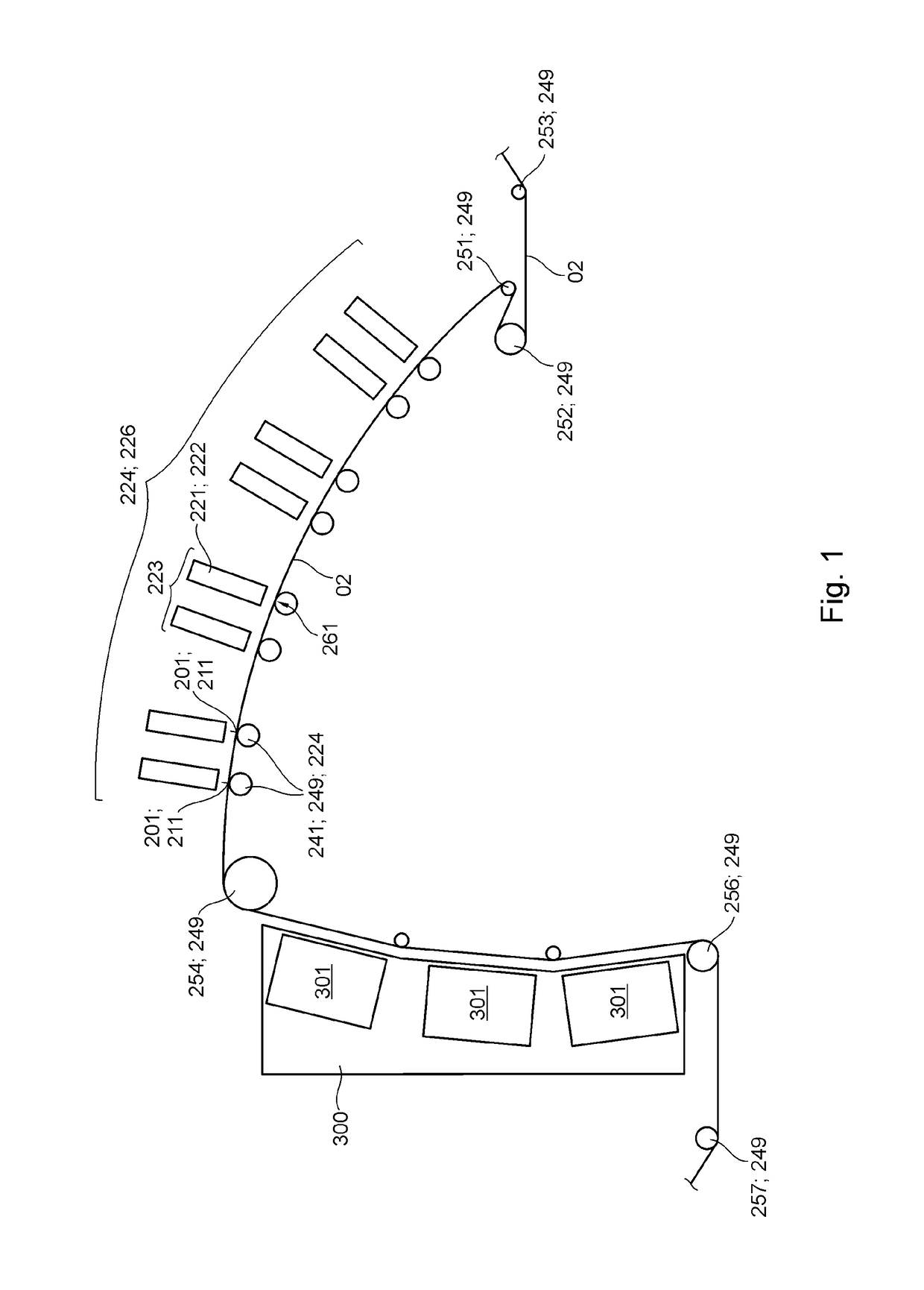
[0029]Further preferably, the printing assembly is alternatively or additionally characterized by the fact that a plurality, or even more preferably all of the at least two and preferably at least five guide elements that together define said provided transport path in the region of the printing section are in contact with a total of at least two lateral support elements and at least one inner support element at three locations, which are spaced from one another in the transverse direction and are preferably embodied as bearing regions, thereby fixing said guide elements in position, the plurality of guide elements or more preferably all of the guide elements being in contact with the same lateral and/or inner support elements. This also produces a supporting effect on the guide elements between the outer ends of the guide elements; as a result, the guide elements have a decreased tendency, or even no tendency at all, to be deflected by the force of gravity and/or by web tension. Such deflection would otherwise impact the distance between nozzles and printing substrate, in particular. In this manner, high print i

Problems solved by technology

In the inkjet printing method, for example, particularly when water-based inks are used, the printing substrate can become deformed, for example, forming ripples.
Such ripples can entail the

Method used


Image

  • Printing assembly
  • Printing assembly
  • Printing assembly

Examples


first embodiment

[0119]In connection with pivot device 279, and as a part of the at least one pivot device 279, for example, at least one linear guide that is flexible, in particular pivotable with respect to its linear axis of movement is provided, along which, for example, at least one slide element is guided, or which further preferably comprises at least one piston that is pivotable relative to stand 283. The piston engages, for example, at a connecting point on the at least one support element 273; 274 and / or the at least one cross-member 277 and / or the at least one support frame 276, the connecting point preferably being pivotable about the first common pivot axis 281. When the at least one support element 273; 274 and / or the at least one cross-member 277 and / or the at least one support frame 276 and / or the at least one guide element 241 executes a pivoting movement, the alignment of the linear axis of movement of the linear guide then also changes.

second embodiment

[0120]In connection with pivot device 279, for example, as part of the at least one pivot device 279, at least one linear guide 287 that is preferably constant with respect to its linear axis of movement is preferably provided, along which at least one slide element is preferably guided. The at least one slide element is preferably assigned to a connecting point 288 of the at least one support element 273; 274 and / or the at least one cross-member 277 and / or the at least one support frame 276, and ensures that said connecting point 288 travels a substantially linear path during movement of the guide elements 241 and / or the at least one support element 273; 274 and / or the at least one cross-member 277 and / or the at least one support frame 276 between the working position and the maintenance position. The provision of the two common pivot axes 281; 282 enables a linear guidance of said connecting point 288 of the at least one support element 273; 274 and / or the at least at least one cr...


PUM


Abstract

The invention relates to a printing assembly which has print heads, each of which specifies application positions for printing fluid. A transport path is provided for the printing substrate through the printing assembly and is defined by at least two guide elements of the printing assembly. A printing section of the transport path begins at a first application position and ends at a last application position. At least one of the guide elements is in contact with a total of at least two lateral support elements and with at least one inner support element at three points that are spaced from one another in a transverse direction, the position of that guide element being thereby defined. The inner support element is arranged such that it is or can be rigidly connected to at least one of the lateral support elements. The lateral support elements can be embodied as part of a support frame, which support frame has at least one cross-member that is different from the guide elements, that at least one cross-member extending in the transverse direction and ensuring a constant relative positioning of the lateral support elements.

Description

CROSS-REFERENCE TO RELATED APPLICATIONS[0001]This application is the U.S. National Phase, under 35 U.S.C. §371, of PCT / EP2015 / 077329, filed Nov. 23, 2015; published as WO2016 / 091563A1 on Jun. 16, 2016 and claiming priority to DE 10 2014 225 206.7 filed Dec. 9, 2014, the disclosures of which are expressly incorporated herein by reference.FIELD OF THE INVENTION[0002]The present invention relates to a printing assembly. The printing assembly has at least two print heads, each of which specifies application positions for printing fluid. A transport path is provided for a printing substrate through the printing assembly and is defined by at least two guide elements of the printing assembly. A printing section of the transport path, which is provided for the printing substrate, begins at a first application position in the printing assembly, continues along that so-provided transport path, and ends at a last application position in the printing assembly along the so-provided transport pat...

Claims


Application Information

Patent Timeline
IPC IPC(8): B41J15/04B41J11/00
CPCB41J11/001B41J15/046
Inventor WANDER, STEFANREDER, WOLFGANGSCHAFER, KARL
Owner KOENIG & BAUER AG
Why Eureka
Try Eureka