Hybrid tubular lattice tower assembly for a wind turbine

a technology of tubular tower and wind turbine, which is applied in the direction of wind turbines, mechanical equipment, machines/engines, etc., can solve the problems of inconvenient transportation of tubular tower sections to the site, difficulty in transporting tubular tower sections, and inability to meet the requirements of a dedicated road

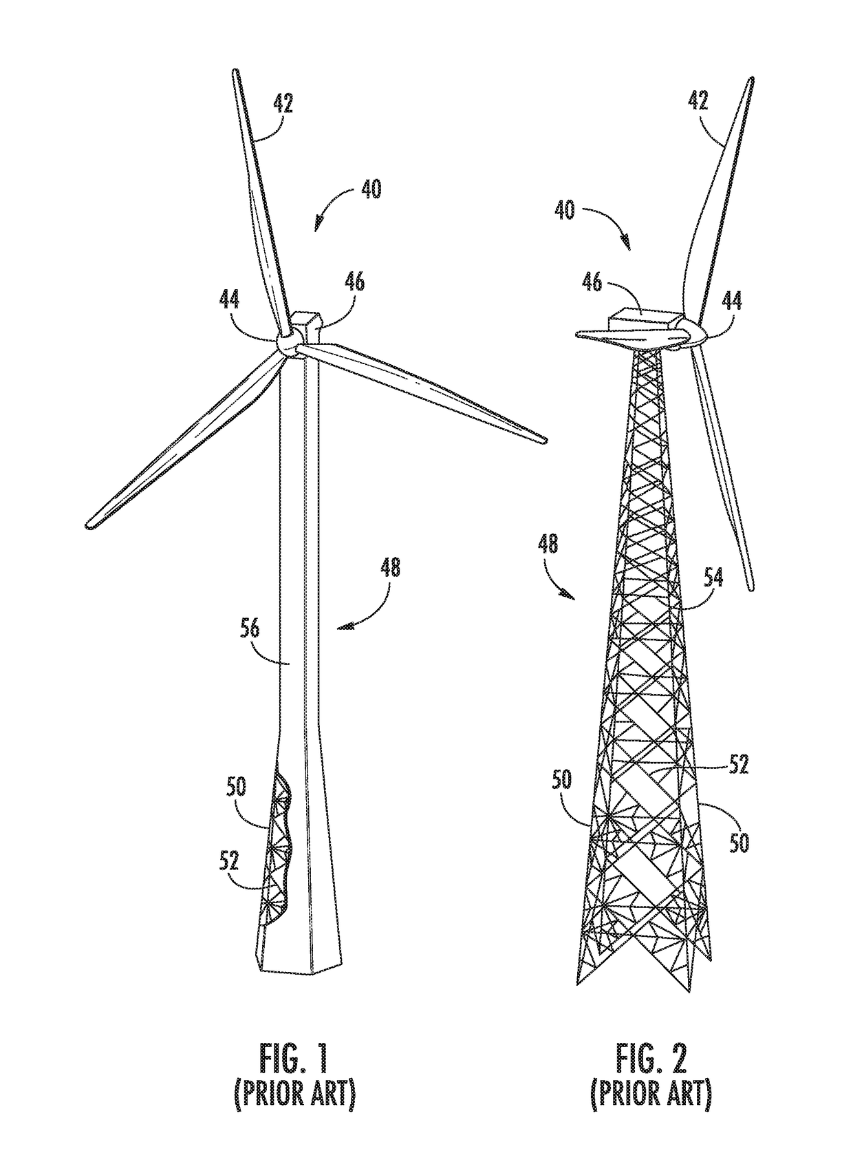
Active Publication Date: 2017-11-09
GENERAL ELECTRIC CO
View PDF19 Cites 12 Cited by
  • Summary
  • Abstract
  • Description
  • Claims
  • Application Information

AI Technical Summary

Benefits of technology

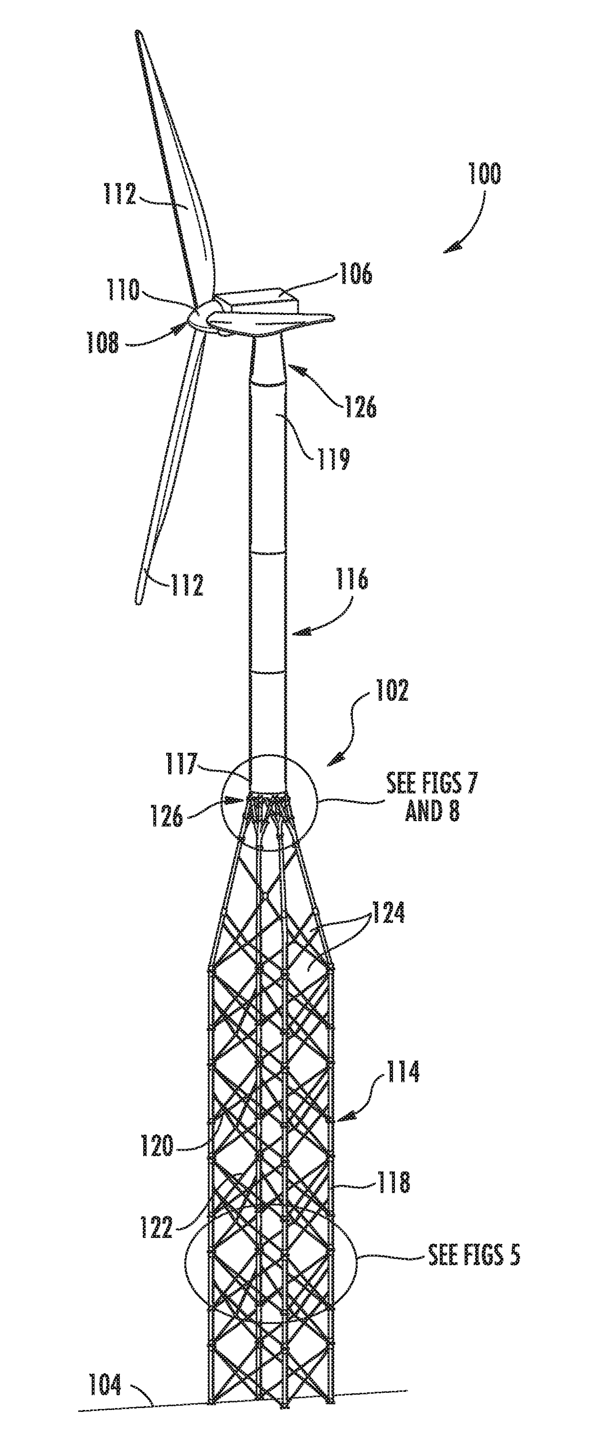
[0008]In one aspect, the present disclosure is directed to a tower assembly for a wind turbine. The tower assembly includes a lattice tower portion, a tubular tower portion, and a transition region therebetween. The lattice tower portion includes a plurality of structural members connected together to define an open lattice tower. Further, the structural members include a plurality of supports and a plurality of cross-support members. The cross-support members are connected between the supports so as to define one or more openings. The tubular tower portion includes a lower portion and an upper portion. The first transition region includes a single-piece connection structure, a plurality of arm members, and a plurality of node connectors. The connection structure has a circumferential body configured to receive the lower portion of the tubular tower portion therein. Thus, the node connectors are configured to join the plurality of supports of the lattice tower portion to the connection structure via the plurality of arm members.

Problems solved by technology

However, tubular poles use more steel than the lattice structure, resulting in a cost disadvantage with rising prices of steel.
For example, transporting the tubular tower sections to the site can be challenging because the sections can be twenty plus meters long and over four meters in diameter.
As such, in some instances, a dedicated road is needed, but may not be possible.

Method used


Image

  • Hybrid tubular lattice tower assembly for a wind turbine
  • Hybrid tubular lattice tower assembly for a wind turbine
  • Hybrid tubular lattice tower assembly for a wind turbine

Examples


Embodiment Construction

[0037]Reference now will be made in detail to embodiments of the invention, one or more examples of which are illustrated in the drawings. Each example is provided by way of explanation of the invention, not limitation of the invention. In fact, it will be apparent to those skilled in the art that various modifications and variations can be made in the present invention without departing from the scope or spirit of the invention. For instance, features illustrated or described as part of one embodiment can be used with another embodiment to yield a still further embodiment. Thus, it is intended that the present invention covers such modifications and variations as come within the scope of the appended claims and their equivalents.

[0038]Generally, the present subject matter is directed to a hybrid tower assembly for a wind turbine. The tower assembly includes a lattice tower portion, a tubular tower portion, and a transition region therebetween. The lattice tower portion includes a p...


PUM


Abstract

The present disclosure is directed to a tower assembly for a wind turbine. The tower assembly includes a lattice tower portion, a tubular tower portion, and a transition region therebetween. The lattice tower portion includes a plurality of structural members connected together to define an open lattice tower. Further, the structural members include a plurality of supports and a plurality of cross-support members. The cross-support members are connected between the supports so as to define one or more openings. The tubular tower portion includes a lower portion and an upper portion. The first transition region includes a single-piece connection structure, a plurality of arm members, and a plurality of node connectors. The connection structure has a circumferential body configured to receive the lower portion of the tubular tower portion therein. Further, the node connectors join the plurality of supports of the lattice tower portion to the connection structure via the plurality of arm members.

Description

FIELD OF THE INVENTION[0001]The present invention relates generally to wind turbines, and more particularly to an improved hybrid tubular lattice tower assembly for a wind turbine.BACKGROUND OF THE INVENTION[0002]Conventional wind turbine towers typically include a tubular pole or a lattice structure to support a wind turbine at a considerable height to capture wind energy. The tubular pole configuration is relatively more simple and easier to assemble than the lattice structure. However, tubular poles use more steel than the lattice structure, resulting in a cost disadvantage with rising prices of steel.[0003]Thus, lattice tower structures can have potential as an alternative to the tubular poles, especially for higher hub height applications and for wind turbines located in wind farms having challenging logistic requirements. For example, transporting the tubular tower sections to the site can be challenging because the sections can be twenty plus meters long and over four meters ...

Claims


Application Information

Patent Timeline
Patent Type & Authority Applications(United States)
IPC IPC(8): F03D13/20E04H12/12E04H12/10E04H12/08E04C3/34F03D1/06E04C3/32
CPCF03D13/20E04H12/085E04H12/10F03D1/0666E04C3/34E04C3/32E04H12/12E04C3/36E04H2012/006F05B2240/912F05B2240/9121Y02E10/728Y02E10/72F03D1/0658
Inventor V, RAGHUNANDAN CRON, GIRIDHAR NAGRAJBENNURI, VAJRALINGAM
Owner GENERAL ELECTRIC CO
Why Eureka
Try Eureka