Road noise masking system for a vehicle

a technology for masking systems and vehicles, applied in the field of vehicles, can solve problems such as unsatisfactory sounds, undesirable noise generation, and detracting from the overall enjoyment of the vehicl

Inactive Publication Date: 2017-11-09
GM GLOBAL TECH OPERATIONS LLC
View PDF4 Cites 3 Cited by
  • Summary
  • Abstract
  • Description
  • Claims
  • Application Information

AI Technical Summary

Benefits of technology

[0003]In accordance with an exemplary embodiment, a method of masking road noise for a vehicle includes monitoring, through a processor, one or more vehicle mounted transducers for noise produced by an interaction between the vehicle and a road surface, detecting, through the processor, an audible signal having one of an undesirable frequency and an undesirable magnitude associated with the interaction between the vehicle and the road surface, generating, through the processor, a masking signal having a frequency that will mask the audible signal having the one of the undesirable frequency and undesirable magnitude, and emitting the masking signal through one or more vehicle speakers.
[0004]In accordance with another aspect of an exemplary embodiment, a road noise masking system for a vehicle includes a controller having a non-volatile memory, and a computer processor unit (CPU) having a computer readable program code embodied therewith. The computer readable program code, when executed by the CPU, causes the CPU to monitor, through the CPU, one or more vehicle mounted transducers for noise produced by an interaction between the vehicle and a road surface, detect, through the CPU, an audible signal having at least one of an undesirable frequency and an undesirable magnitude associated with the interaction between the vehicle and the road surface, generate, through the CPU, a masking signal having a frequency that will mask the audible signal having the one of th

Problems solved by technology

Vehicle owners may be concerned with undesirable sounds that may exist in a vehicle interior.
Often times, the undesirable noise may be generated

Method used


Image

  • Road noise masking system for a vehicle
  • Road noise masking system for a vehicle
  • Road noise masking system for a vehicle

Examples


Embodiment Construction

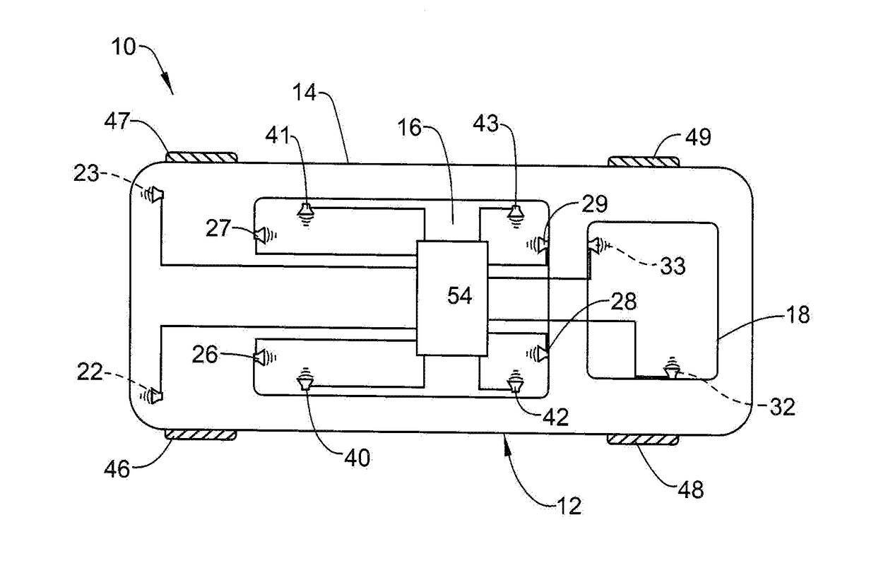
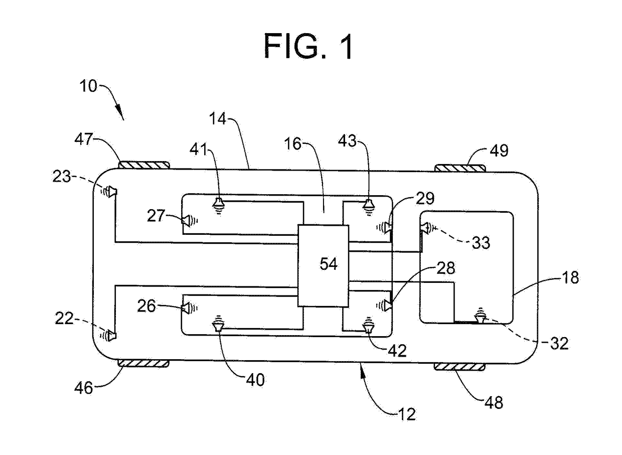
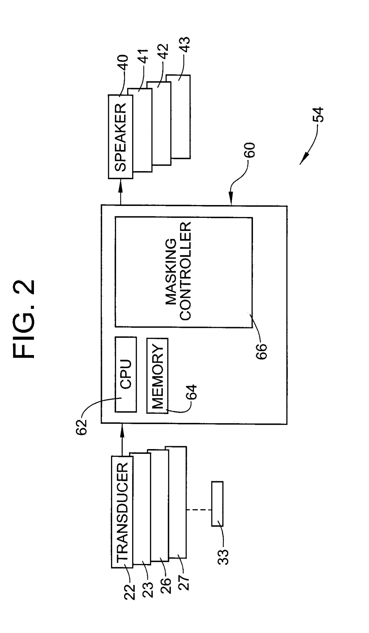
[0012]The following description is merely exemplary in nature and is not intended to limit the present disclosure, its application or uses. It should be understood that throughout the drawings, corresponding reference numerals indicate like or corresponding parts and features. As used herein, the term “module” or “unit” refers to an application specific integrated circuit (ASIC), a field programmable gate array (FPGA), an electronic circuit, an electronic computer processor (shared, dedicated, or group) and memory that executes one or more software or firmware programs, a hardware microcontroller, a combinational logic circuit, and / or other suitable components that provide the described functionality. When implemented in software, a module can be embodied in memory as a non-transitory machine-readable storage medium readable by a processing circuit and storing instructions for execution by the processing circuit for performing a method.

[0013]A vehicle, in accordance with an exemplar...


PUM


Abstract

A method of masking road noise for a vehicle includes monitoring, through a processor, one or more vehicle mounted transducers for noise produced by an interaction between the vehicle and a road surface, detecting, through the processor, an audible signal having one of an undesirable frequency and an undesirable magnitude associated with the interaction between the vehicle and the road surface, generating, through the processor, a masking signal having a frequency that will mask the audible signal having the one of the undesirable frequency and undesirable magnitude, and emitting the masking signal through one or more vehicle speakers.

Description

FIELD OF THE INVENTION[0001]The subject invention relates to the art of vehicles and, more particularly, to a road noise masking system for a vehicle.BACKGROUND[0002]Vehicle owners may be concerned with undesirable sounds that may exist in a vehicle interior. Often times, the undesirable noise may be generated by an interaction between vehicle tires and a road surface. Variations in a road surface including changes in surface material, surface structure and the like produce varying sounds when engaged by the vehicle tires. Undesirable noises may be transmitted and amplified through various vehicle components including body and suspension components. When present, undesirable noise may detract from an overall enjoyment of the vehicle. Accordingly, it is desirable to provide a cost-effective system that promotes a more enjoyable interior environment for the vehicle.SUMMARY OF THE INVENTION[0003]In accordance with an exemplary embodiment, a method of masking road noise for a vehicle in...

Claims


Application Information

Patent Timeline
IPC IPC(8): G10K11/175
CPCG10K2210/1282G10K11/175B60R16/037G10K11/178G10K11/1752
Inventor VALERI, FRANK C.REILLY, SCOTT M.STIRLEN, CHRISTOPHER A.
Owner GM GLOBAL TECH OPERATIONS LLC
Why Eureka
Try Eureka