Installation and method for winding an elongated flexible inductor

Active Publication Date: 2017-11-09
PREMO
View PDF6 Cites 2 Cited by
  • Summary
  • Abstract
  • Description
  • Claims
  • Application Information

AI Technical Summary

Benefits of technology

[0028]This installation therefore allows a flexible inductor to be fed to said conveyance surface of the first conveyor, to be retained on said conveyance surface while it is conveyed in the conveyance direction by means of said retaining device, and for an end of said flexible inductor to hang over the end of the first conveyor, entering a space that is susceptible to being accessed by the mentioned winding means that will wind a lead wire around the flexible inductor as said flexible inductor is conveyed forward in the conveyance direction by the first conveyor.

Problems solved by technology

Said flexible property of the core and its dimensions cause it to bend during the winding operation, leading to an incorrect winding.
However, none of the mentioned documents describes or proposes a solution for the problem of how to wind a lead wire onto an elong

Method used


Image

  • Installation and method for winding an elongated flexible inductor
  • Installation and method for winding an elongated flexible inductor
  • Installation and method for winding an elongated flexible inductor

Examples


Example

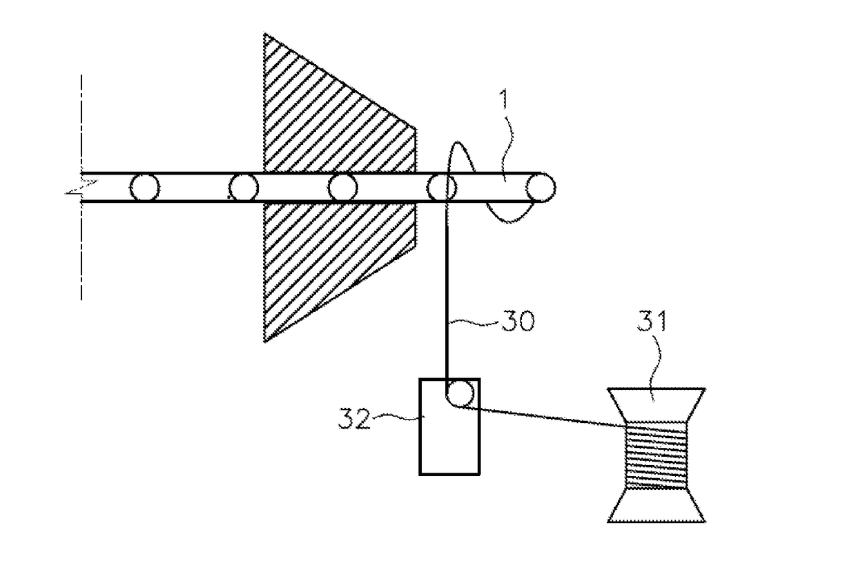
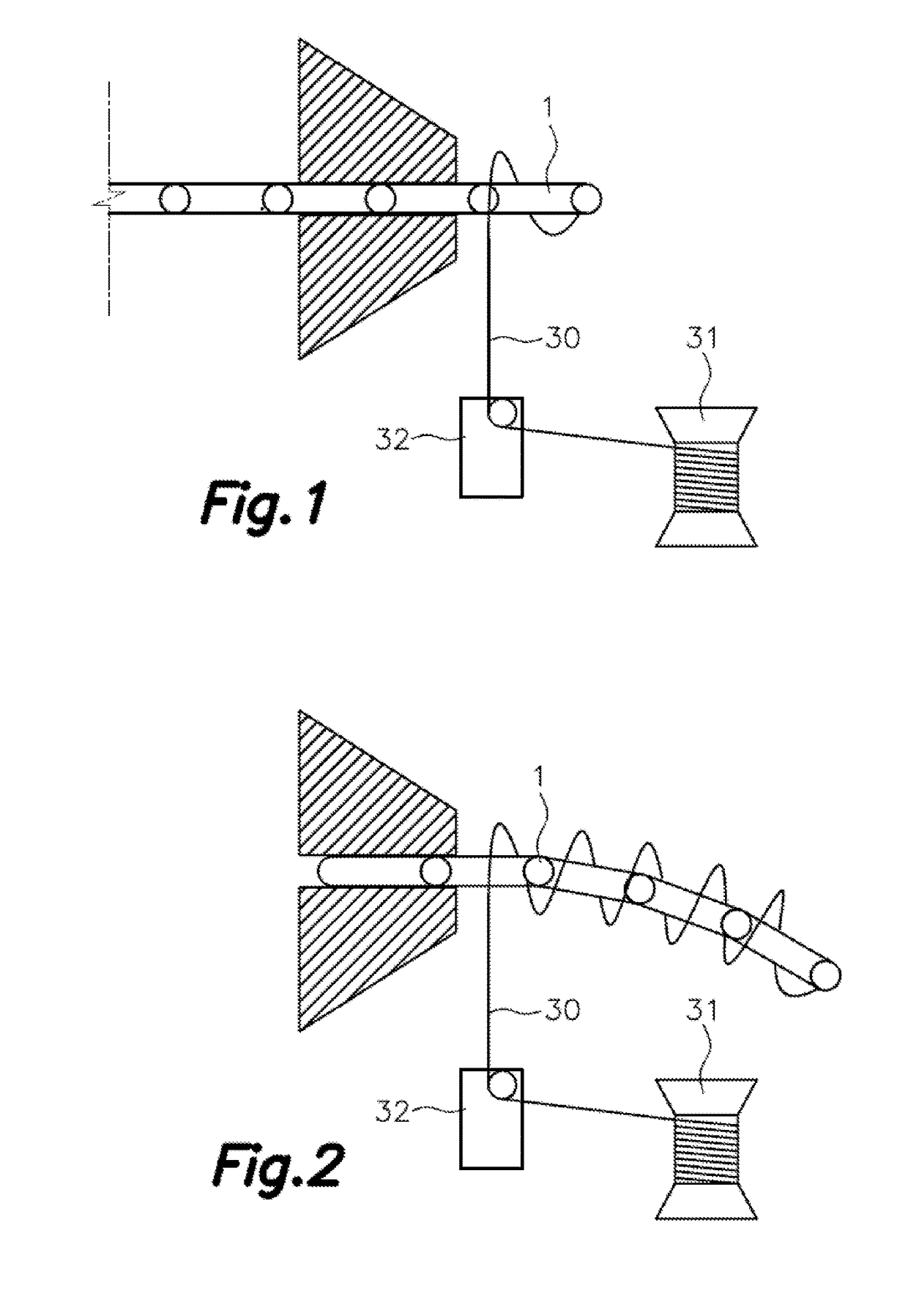
[0055]FIGS. 1 and 2 illustrate the technical problem the present invention solves. Said problem consists of a flexible inductor 1 bending while a lead wire 30 is being wound on it, said flexible inductor 1 being held such that it is overhanging. In said FIG. 2 it can be seen how the overhanging segment of the flexible inductor 1 bends when it reaches a given length, which can cause defects when the lead wire 30 is being wound on it.

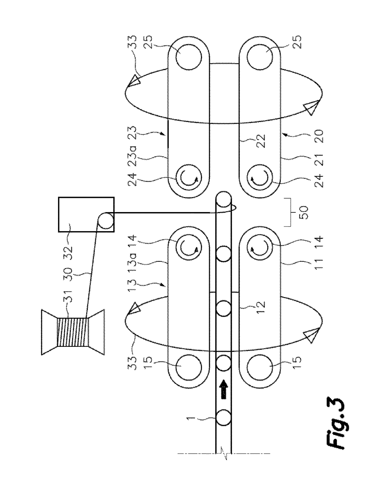
[0056]Therefore, FIGS. 3, 4 and 5 show a non-limiting illustrative embodiment of an installation for winding an elongated flexible inductor 1 where the mentioned technical problem has been solved.

[0057]Said installation that is shown has a first conveyor 11 formed by an endless band spanning between a drive roller 14 and a driven roller 15, such that the rotation of the drive roller 14 causes the movement of the endless band like a conveyor belt, defining a conveyance direction.

[0058]One of the faces of said endless band determines a conveyance surface 12...


PUM


Abstract

The present invention relates to an installation and method for winding an elongated flexible inductor, the proposed installation comprising a first conveyor (11) for moving the elongated flexible inductor (1) in a conveyance direction, supported on a conveyance surface (12); a retaining device (13) for fixing the flexible inductor (1) to said conveyance surface (12); winding means for winding a metallic lead wire (30) around a section of the flexible inductor (1) not supported on said conveyance surface (12), comprising at least one lead wire reel (31), a lead wire feed device (32) and a turning device (33), a holding device (20) provided for holding a portion of the already wound flexible inductor (1), being located opposite and spaced from the end of the first conveyor by a minimum predetermined distance, defining a winding area (50) susceptible to being accessed by said lead wire feed device (32); said turning device (33) causing the simultaneous turning of the first conveyor and of said holding device.

Description

FIELD OF THE ART[0001]The present invention is comprised in the field of keyless door opening or entry systems, which have a particular application in the automobile sector, in which they are also applied to controlling the electronic immobilizer for starting the engine. This “keyless” entry system (KES or also referred to as Passive Keyless Entry (PKE)) is based on the use of a remote control device emitting wireless signals and on the arrangement in the actual vehicle of 3 or more antennas the function of which is to detect the presence (by sensing the mentioned wireless signals) of the mentioned remote control device the user carries within a perimeter of 1.5 m or more around the vehicle. After said device is detected, the doors open or unlock, and the options of starting up and cutting off the engine, adjusting the rearview and side mirrors, adjusting the motor-operated seats, and switching on the courtesy light, among other possible functions, can also be enabled.[0002]The use ...

Claims


Application Information

Patent Timeline
IPC IPC(8): H01F41/064H01F41/096B65G15/16H01F27/28
CPCH01F41/064B65G15/16H01F41/096H01F27/2823B65H81/06H01F38/14H01Q1/3241H01Q7/06H01F41/066H01F41/098H01Q7/08H01F41/073H01F27/2847H01F2017/006
Inventor ROJAS-CUEVAS, ANTONIONAVARRO-PEREZ, FRANCISCO EZEQUIELCANETE-CABEZA, CLAUDIOGARCIA-VACAS, FRANCISCO
Owner PREMO
Why Eureka
Try Eureka