
Power storage module

a technology of power storage module and power storage element, which is applied in the direction of cell components, final product manufacturing, sustainable manufacturing/processing, etc., can solve the problems of increased production cost and higher number of parts, and achieve the effect of reducing the production cost of the electricity storage module and reliably pressing or pressing the power storage element group

Active Publication Date: 2017-11-09
AUTONETWORKS TECH LTD +2
View PDF3 Cites 4 Cited by
  • Summary
  • Abstract
  • Description
  • Claims
  • Application Information

AI Technical Summary

Benefits of technology

The present invention provides an improved design for an electricity storage module. By sealing the gap between the guide and guided portions, a separate sealing member is not required, reducing the number of parts and production cost. The guided portion can be securely brought into close contact with the guide portion. Additionally, a pressurizing member can be used to prevent swelling of the electricity storage element due to gas production. The pressing and pressurizing members are elastically engaged, enabling reliable pressure application on the power storage element group.

Problems solved by technology

However, according to the above-described technique, since the gap between the vent and the duct is sealed by the sealing member, the number of parts is higher and the production cost increases.

Method used


Image

  • Power storage module
  • Power storage module
  • Power storage module

Examples


embodiment 1

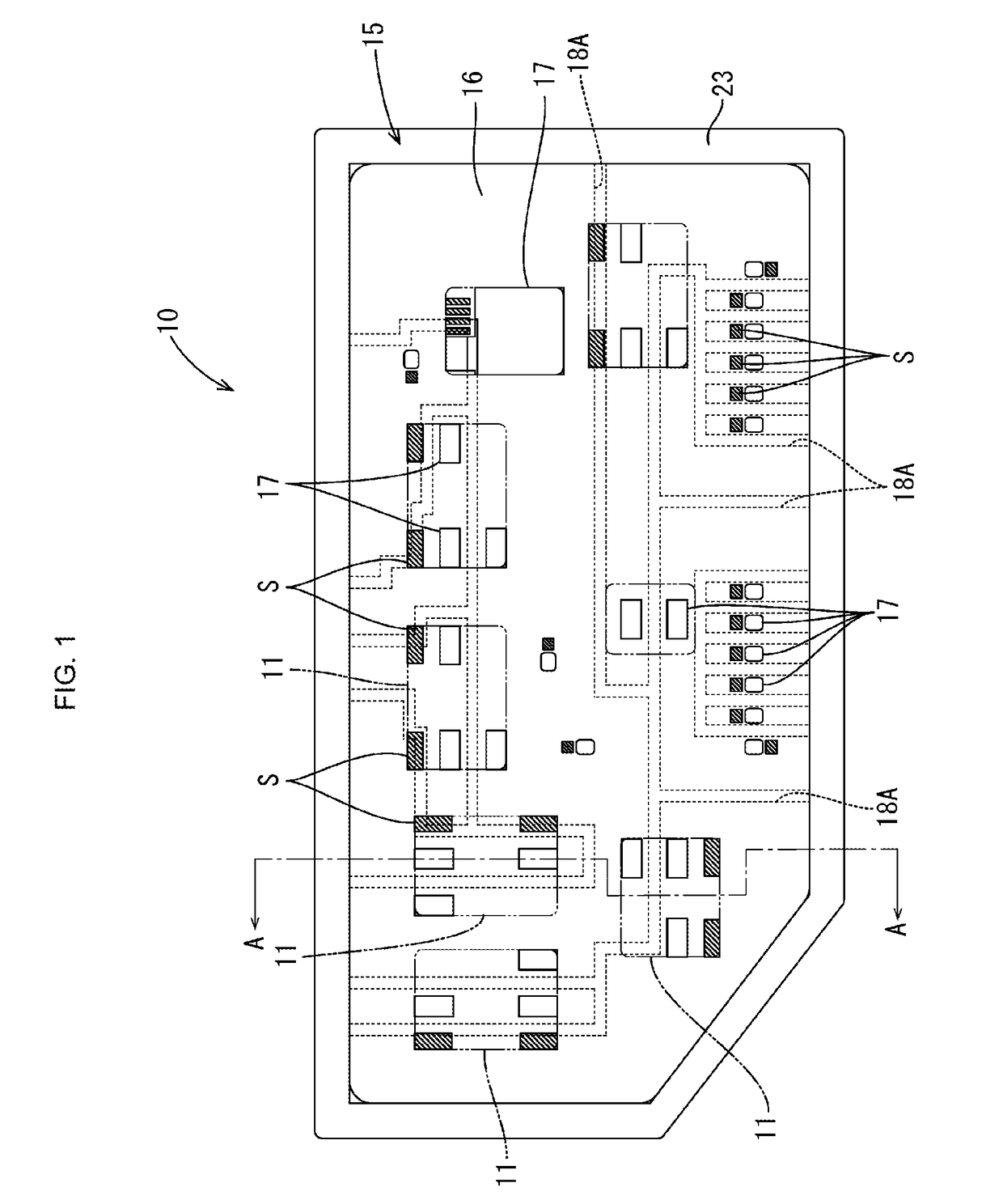
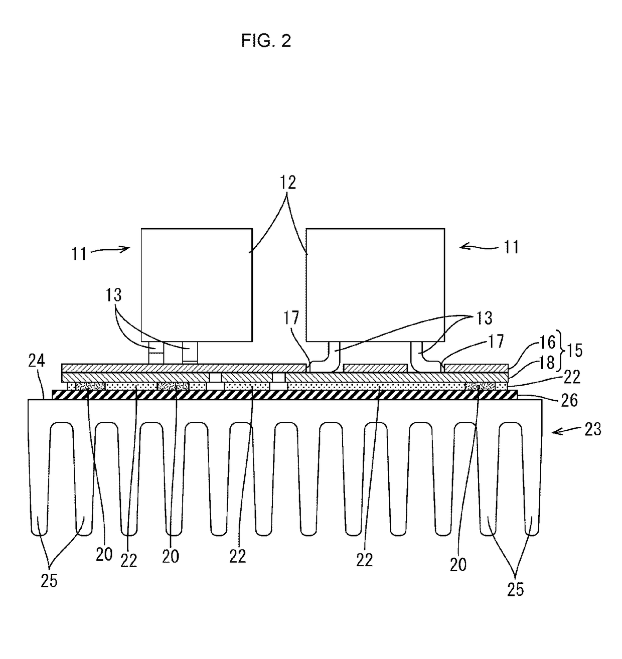
[0032]Embodiment 1 of the present invention will be described with reference to FIGS. 1 to 15. An electricity storage module 10 according to the present embodiment includes an electricity storage element group 12 composed of multiple electricity storage elements 11, and a cover 13 that is attached to the electricity storage element group 12. The electricity storage module 10 is used as a power source or an auxiliary power source in a vehicle such as an automobile, an electric automobile, or a hybrid car. Note that in the following description, the Z direction is upward, the Y direction is rightward, and the X direction is frontward.

[0033]Note that the above-described directions are used for convenience in the description of the embodiment, and the electricity storage module 10 can be attached in any orientation to a vehicle.

[0034]As shown in FIG. 1, the electricity storage element 11 has a flat cuboid shape. Each electricity storage element 11 has a pair of electrode terminals 14 co...


PUM

PropertyMeasurementUnit
internal pressureaaaaaaaaaa
shapeaaaaaaaaaa
pressureaaaaaaaaaa

Abstract

Provided is an electricity storage module including an electricity storage element group composed of multiple electricity storage elements having exhaust ports that discharge gas produced therein, and a cover attached to the electricity storage element group, wherein the electricity storage element group has exhaust surfaces on which the exhaust ports are arranged, and the cover is attached so as to cover the exhaust surfaces, guide walls that surround the exhaust ports in the form of loops are formed in the respective electricity storage elements, guide ribs that come into close contact with the guide portions and fit therein are formed on an opposing surface of the cover that opposes the exhaust surfaces, and the cover is provided with a duct that communicates with the exhaust ports and through which gas discharged from the exhaust ports passes.

Description

CROSS-REFERENCE TO RELATED APPLICATIONS[0001]This application is the U.S. national stage of PCT / JP2015 / 082987 Nov. 25, 2015, which claims priority of Japanese Patent Application No. JP 2014-238874 filed Nov. 26, 2014.TECHNICAL FIELD[0002]The present invention relates to an electricity storage module.BACKGROUND[0003]Conventionally, an electricity storage module disclosed in JP 2011-108653A has been known as an electricity storage module having a single-cell battery group composed of multiple single-cell batteries. A duct through which gas produced by electricity storage elements passes is attached to the single-cell battery group of the electricity storage module.[0004]A vent for discharging gas produced in the electricity storage elements is formed in the electricity storage element. A gap between the vent and the duct is sealed by a sealing member.[0005]However, according to the above-described technique, since the gap between the vent and the duct is sealed by the sealing member, ...

Claims


Application Information

Patent Timeline
Patent Type & Authority Applications(United States)
IPC IPC(8): H01G11/10H01M10/0525H01M2/12H01M10/34H01G11/78H01M50/209H01M50/227H01M50/271H01M50/367
CPCH01G11/10H01G11/78H01M2/1252H01M10/345H01M10/0525H01G11/14H01M10/0481H01G11/18H01G11/82H01G2/06H01G2/08Y02E60/10Y02P70/50H01M50/367H01M50/209H01M50/227H01M50/271
Inventor MORITA, KYOHEISUMIDA, TATSUYA
Owner AUTONETWORKS TECH LTD
Learn More