Check patentability & draft patents in minutes with Patsnap Eureka AI!

Vehicular torque control device and torque control method

a technology of torque control device and control device, which is applied in the direction of electric devices, braking systems, braking components, etc., can solve the problems of vehicle body instability, driver anxiety, and safety problems, so as to avoid the overturning of the vehicle, increase the output torque, and prevent the vehicle body from being unstable

Active Publication Date: 2017-11-16
ROBERT BOSCH GMBH
View PDF2 Cites 5 Cited by
  • Summary
  • Abstract
  • Description
  • Claims
  • Application Information

AI Technical Summary

Benefits of technology

The present invention provides a vehicle torque control system that prevents the vehicle body from becoming unstable when the engine brake is operated. This is accomplished by early on initiating torque control in response to sudden clutch connection or gear shifts, before the rear wheel slips and causes the vehicle to become unstable. The system detects the engine speed and the driving wheel rotating speed, and calculates a current driving wheel rotating speed based on a predetermined engine speed in each gear stage of the transmission. The output torque is controlled to match the theoretical driving wheel rotating speed when a certain threshold value is met. This enables quicker intervention in torque control and prevents the vehicle body from becoming unstable. Overall, the invention improves stability and reliability of the vehicle.

Problems solved by technology

However, in a case of a motorcycle, when the slipping state is generated at the rear wheel (driving wheel) as the gear is shifted down and the engine brake is suddenly operated, similarly to the device described in Japanese Patent No. 3454011, in the configuration in which the control is initiated at the moment when the slipping state is generated at the rear wheel (driving wheel), there are many cases where the vehicle body is already in an unstable state and a driver feels an anxiety.
In this case, it is assumed that it becomes too late to initiate the control after detecting the slip ratio of the rear wheel (driving wheel), and in the worst case, there is a problem in terms of safety since a situation where the vehicle is overturned is assumed.

Method used


Image

  • Vehicular torque control device and torque control method
  • Vehicular torque control device and torque control method
  • Vehicular torque control device and torque control method

Examples


Embodiment Construction

[0033]Next, an embodiment of a torque control device according to the present invention will be described hereinafter with reference to the drawings. In addition, in the following embodiment, examples of torque control means 300 include an antilock brake system (ABS), a drag torque control (DTC), and an electrical control unit (ECU).

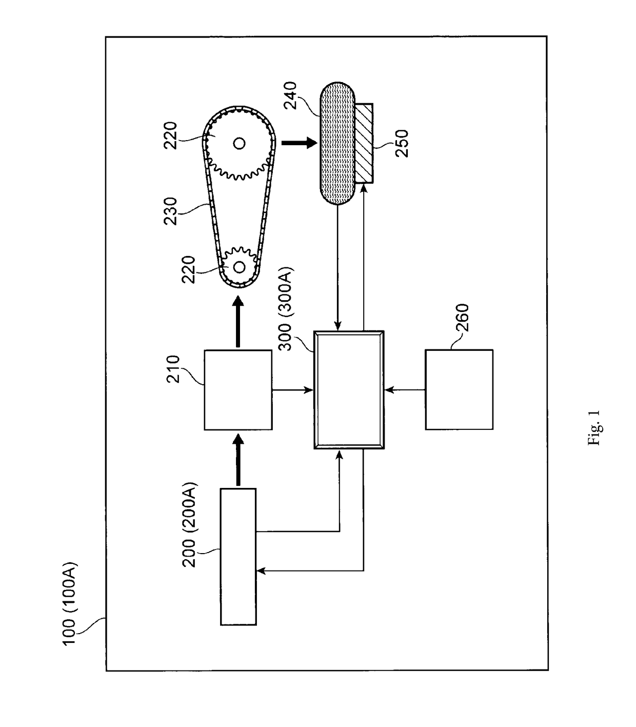
[0034]FIG. 1 schematically illustrates a configuration of a torque control device 100 of the present invention, and is a block diagram of the torque control device 100 which has a vehicle engine 200, a gear box 210, a plurality of sprockets 220 and 220, a belt 230, such as a link plate chain, which is wound around the sprockets 220 and 220, a driving wheel 240 which corresponds to a rear wheel of a vehicle, a brake 250 which brakes the driving wheel 240, the torque control means 300 for controlling the torque when shifting down a gear, and an external information source 260 including various sensors that electrically connected to the torque control means...


PUM


Abstract

There is provided a configuration, including a storage unit that stores a theoretical driving wheel rotating speed based on a correspondence relationship with a predetermined engine speed in each gear stage of a transmission of a vehicle; gear stage detection means for detecting the gear stage when currently travelling; engine speed detection means for detecting an engine speed; driving wheel rotating speed detection means for detecting a driving wheel rotating speed; and torque control means for controlling output torque, in which the output torque is increased so that a current driving wheel rotating speed becomes close to the theoretical driving wheel rotating speed when a relative value of a calculated value which is calculated by using the detected driving wheel rotating speed with respect to a calculated value which is calculated by using the theoretical driving wheel rotating speed is equal to or greater than a first threshold value.

Description

BACKGROUND OF THE INVENTION[0001]The present invention relates to a vehicular torque control device and a torque control method for controlling output torque when particularly sudden clutch connection operation or a shift-down of a gear is performed.[0002]In the related art, an engine output control device of a vehicle, such as a car, generally employs a configuration for detecting a slipping state of a driving wheel, initiating control at the moment when the slipping state is generated in the driving wheel, restarting supply of fuel to an engine by releasing a stopped state of the supply of the fuel, reducing an effect of an engine brake by increasing an engine speed, and preventing generation of a slip of the driving wheel.[0003]When a braking force by the engine brake is exerted, the slip at the driving wheel, for example, a rear wheel of a rear wheel driving vehicle, is likely to be generated as a load ratio which acts on the front and rear wheels that support a load of a vehicl...

Claims


Application Information

Patent Timeline
Patent Type & Authority Applications(United States)
IPC IPC(8): B60L3/10
CPCB60L3/106B60L2240/486B60L2240/421B60L2240/461B60L2240/423B60L2240/507B60Y2200/91B60Y2300/18175B60Y2300/60B60K28/16B60T8/1706B60T8/175B60W30/18172B60T2250/042B60T2270/211B60W30/02B60W2510/0638B60W2510/1005B60W2520/28B60W2710/0666B60W2510/0208B60W2540/10Y02T10/72B60W10/10
Inventor WATANABE, TAKUYA
Owner ROBERT BOSCH GMBH
Features
  • R&D
  • Intellectual Property
  • Life Sciences
  • Materials
  • Tech Scout
  • Unparalleled Data Quality
  • Higher Quality Content
  • 60% Fewer Hallucinations
Learn More