Sheet feeding apparatus and image forming apparatus

Inactive Publication Date: 2017-11-16
CANON KK
View PDF1 Cites 0 Cited by
  • Summary
  • Abstract
  • Description
  • Claims
  • Application Information

AI Technical Summary

Benefits of technology

The present invention is about a device that feeds sheets of paper and a machine that makes images on paper. The device doesn't require switching between power and discharge, which means that it can create static force and discharge at the same time. This prevents a decrease in productivity.

Problems solved by technology

In such friction separation configurations, noise caused during the feeding operation becomes a problem, since sheets are conveyed while applying a large vertical drag to the sheets.
This residual electric charge will deteriorate the electrostatic attraction force of the electrostatic attraction belt, so that it is required to discharge the residual electric charge.
According to the above-mentioned configuration, the voltages are applied to the whole area of the electrostatic attraction belt during the operation of attracting the sheet, so that sufficient discharging effect cannot be achieved by having the discharge portion contact the electrostatic attraction belt in this state.
Therefore, the productivity may be deteriorated significantly.
In an attempt to apply the power feed configuration disclosed in Japanese Patent Application Laid-Open Publication No. 2001-48370 to the apparatus disclosed in Japanese Patent Application Laid-Open Publication No. 2012-140224, since the attraction range is moved up and down, it is difficult to have the power feed brush come into secure contact with electrodes disposed on the electrostatic attraction belt to feed power.

Method used


Image

  • Sheet feeding apparatus and image forming apparatus
  • Sheet feeding apparatus and image forming apparatus
  • Sheet feeding apparatus and image forming apparatus

Examples


first embodiment

[0029]Now, a preferred embodiment of the present invention will be described in detail with reference to the drawings. In the description, the present invention is implemented in an electro-photographic image forming apparatus, but the size, material, shape, relative configuration and the like disclosed in the present embodiments are not intended to restrict the scope of the present invention in any way.

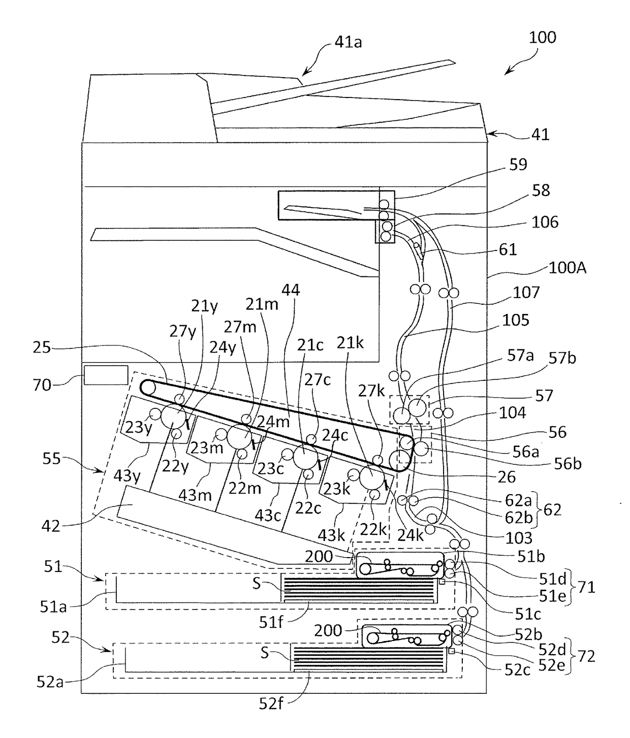
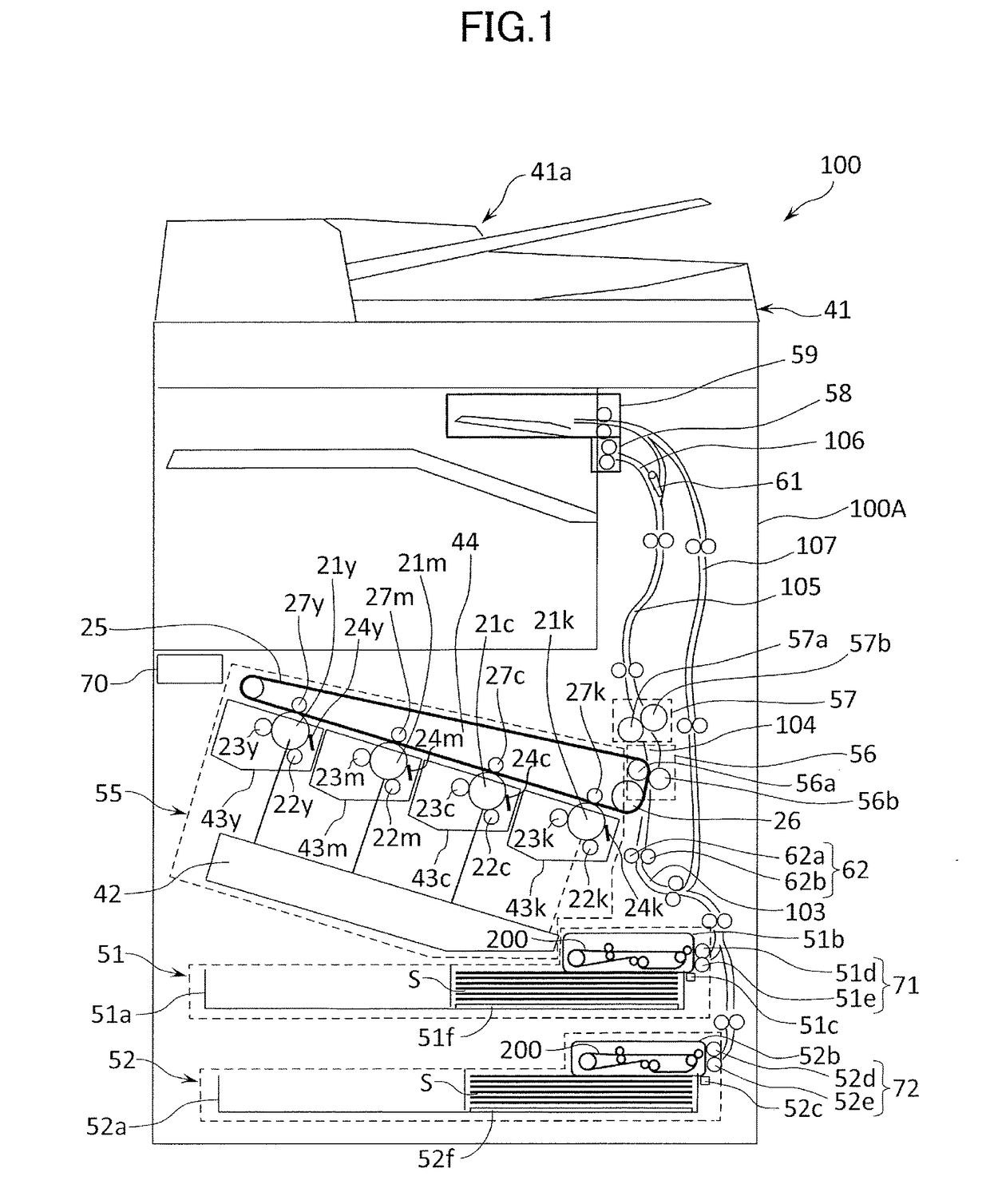
[0030]FIG. 1 is a schematic view illustrating the image forming apparatus having a sheet feeding apparatus according to the present embodiment. In FIG. 1, 100 denotes the image forming apparatus, and 100A denotes an image forming apparatus body (hereinafter referred to as apparatus body). On the upper portion of the apparatus body 100A is arranged an image reader 41, which irradiates light onto a document placed on a platen glass as a document positioning plate and has an image sensor and the like that converts reflected light into digital signals. The apparatus body 100A includes a ...

second embodiment

[0144]Now, a second embodiment of the present invention will be described with reference to FIGS. 12 to 17. In the present embodiment, the same components as the first embodiment are denoted with the same reference numbers, and the descriptions of components having the same configuration and function are omitted.

[0145]In the first embodiment described earlier, power feed to the attraction member 200 is performed from the positive voltage supply portion 265 and the negative voltage supply portion 266 through the first nipping-conveying inner roller 202a, but in the present embodiment, in addition to the above, power is also fed from the second nipping-conveying inner roller 201a.

[0146]FIG. 12 is a view illustrating an configuration of the sheet feeding apparatus 51 according to the present embodiment. In the present embodiment, the positive voltage supply portion 265 and the negative voltage supply portion 266 are connected to both the first nipping-conveying inner roller 202a and t...


PUM


Abstract

A sheet feeding apparatus includes an endless attraction member (200) attracting a sheet and rotating, and the attraction member (200) includes a plurality of electrode pattern areas. Each of the electrode pattern areas includes first and second electrodes (510 and 511) supplied the voltages from a power feed portion respectively. The electrode pattern areas are arrayed in the circumferential direction in such a manner that the electrode pattern areas are electrically insulated each other, and each circumferential direction length of the electrode pattern areas is set shorter than a circumferential direction length, between the power feed portion and the discharge portion, of the attraction member.

Description

TECHNICAL FIELD[0001]The present invention relates to a sheet feeding apparatus and an image forming apparatus, and more specifically, to a configuration to feed a sheet by using an electrostatic attraction force.BACKGROUND ART[0002]In an image forming apparatus such as a copying machine and a printer, many apparatuses adopting a friction separation-type system as a system for conveying sheets from a cassette in which the sheets are stacked. In the friction separation system, a sheet feed roller formed of a rubber material is rotated while being pushed against the sheet stacked in the cassette, so as to convey an uppermost sheet from the sheets stacked on an intermediate plate. In order to prevent multiple feeding where a lower sheet in contact with the uppermost sheet is conveyed with the uppermost sheet, known configurations such as pressing the sheet against a separation pad during conveyance and applying a conveying force in a direction opposite to the conveyance direction with ...

Claims


Application Information

Patent Timeline
IPC IPC(8): B65H7/18B65H3/18
CPCB65H3/18B65H2801/06B65H2515/716B65H2515/702B65H2515/706B65H2404/256B65H2404/28B65H2401/21B65H2404/533B65H3/047B65H7/18B65H2404/25B65H2511/212B65H2515/70B65H2220/01B65H2220/11B65H2220/08
Inventor OKAMOTO, HIDEAKIAOYAMA, TAKESHIHIRATSUKA, TAKASHIHAYASHI, ISAOAOYAGI, TAKAAKIYOSHIDA, YASUMISHIMIZU, HISAE
Owner CANON KK
Why Eureka
Try Eureka