Cell driving type piezoelectric actuator, and method of manufacturing cell driving type piezoelectric actuator

a piezoelectric actuator and cell technology, applied in the direction of positive displacement liquid engines, machines/engines, generators/motors, etc., can solve the problems of affecting the performance of the actuator, affecting the quality of typing/printing, and the generation of crosstalk, etc., to improve the displacement efficiency of the present actuator, increase the response rate, and increase the displacement

Inactive Publication Date: 2007-09-25
NGK INSULATORS LTD
View PDF8 Cites 2 Cited by
  • Summary
  • Abstract
  • Description
  • Claims
  • Application Information

AI Technical Summary

Benefits of technology

[0044]In the cell driving type piezoelectric actuator according to the present invention, as a preferable sub-embodiment of the third embodiment, one may employ a embodiment wherein the piezoelectric operation portions for the respective cell driving bodies are provided on any three combination out of two side walls, a ceiling wall, and a bottom wall or all of them. This is because each of cells having a slit shape is formed by an individual wall portion being composed of two side walls, a ceiling wall, and a bottom wall. As a result, a larger change in the cell volume is attained at the prescribed driving voltage, and this make it possible to further enhance the displacement efficiency of the present actuator.
[0045]In case of one preferable sub-embodiment for the first embodiment of the cell driving type piezoelectric actuator according to the present invention, each piezoelectric operation portion for the actuator includes a laminar piezoelectric body and at least one pair of electrodes both of which are alternately laminated in the height direction of the side wall, thereby the displacement is generated by the piezoelectric vertical effect. Therefore, the strain based on the piezoelectric effect is directly usable, the generation force of displacement is large, and the response rate is fast. Therefore, effects in the reduction of crosstalk and the enhancement of displacement efficiency are large.
[0046]Moreover, in case of a further preferable sub-embodiment of the first embodiment, at least the end portion of each electrode for each cell driving body is embedded in the inside face of the cell constituting the piezoelectric body. Therefore, any type of fluids can be used in principle since the surface of the piezoelectric body that the fluid to be charged into the cell contacts is usually made of chemically remarkably stable ceramic. Furthermore, since the electrode does not contact the fluid charged in the cell during the manufacturing the present actuator, it is not necessary to form the protector film for insulating the electrode regardless of the type of the fluid to be used. This would reduce largely the number of the manufacturing steps. When one employs an embodiment wherein the end portion of each electrode for each cell driving body is embedded no so as to appear both in the internal face and in the outer face of the cell, and no common electrode or wiring is formed on the side wall of the piezoelectric body, one may connect a plurality of cell driving bodies one another through the support bodies in a higher density without lowering the reliability in conductivity of the electrode.
[0047]The preferable sub-embodiment of the second embodiment of the cell driving type piezoelectric actuator according to the present invention is an embodiment in which the piezoelectric operation portion includes a laminar piezoelectric body and at least one pair of electrodes formed on the side surfaces of the piezoelectric body, and the displacement is generated by the piezoelectric transverse effect. In a further preferable sub-embodiment in the second embodiment, a plurality of laminar piezoelectric bodies in each cell driving body are disposed, and the respective laminar piezoelectric bodies thereof are laminated in the width direction of the side wall with sandwiching the respective laminar piezoelectric bodies between the respective electrodes therefor. According to this sub-embodiment, one may make the piezoelectric body thinner. Thus, one may attain a larger displacement and higher generation force at the prescribed driving voltage. When the laminar piezoelectric bodies are laminated to form a plywood-like member, the mechanical strength of the actuator can be enhanced. Therefore, the piezoelectric actuator having a higher durability is attained. Note that the cell driving type piezoelectric actuator according to the present invention is not restricted to the first and second embodiments, and that a cell driving type piezoelectric actuator using a share mode wherein the displacement is caused by applying the driving voltage in a direction crossing a polarized electric field direction of the piezoelectric body at right angle may also be used.
[0048]In the first embodiment of a method for manufacturing a cell driving type piezoelectric actuator according to the present invention, the green sheet lamination method may be used. One may form a via hole or a through hole, and a conductor film to be connected with the electrodes through the via hole or the through hole and to be exposed to each cavity forming surface on each sheet in which the predetermined number of the cavities has been formed before laminating the sheets. If one employs this embodiment, one may complete wiring process of an actuator by forming the electrodes only on the side face of the through hole to be communicated with the electrodes through the respective cavities of the ceramic green laminated body or the fired laminated body obtained by laminating the respective sheets. This obviates a necessity for performing a laborious wiring operation after obtaining the fired laminated body, and the simplification of the manufacturing method can be achieved. Since the electrode(s) formed on the side face of the through hole are connected to the via hole through a plurality of conductor films formed on each sheet, the driving reliability is enhanced without causing the conductive defect. The electrode(s) formed on the side surface of the through hole is connected to the via hole through the conductor film of each sheet, and connected to even the via hole appearing on the surface of the fired laminated body. A terminal electrode can be disposed so as to be connected to the via hole if necessary, and it is easy to connect the piezoelectric actuator to other devices or apparatuses such as a power supply.
[0049]The second and third embodiments of a method for manufacturing a cell driving type piezoelectric actuator according to the present invention include the steps of: preparing a plurality of the cells each of which is a closed space except that the micro-channels are formed at one end; introducing a fluid of a conductor material and / or an insulator material through the micro-channels; bringing the conductor material and / or the insulator material into close contact with the cell forming surface of the wall portion; and forming electrodes on the cell forming surface. Indeed, only an insulator material is used in the case of the second embodiment of the present method. After forming the cell that may be deemed as a substantially closed space, the electrode(s) or the protector film can be formed on the cell forming surface. Therefore, in the case of the second and third embodiments, one does not need the step of forming the electrode(s) or the protector film in the step of laminating the sheets like the green sheet lamination method employed in the first embodiment for a manufacturing method. Accordingly, the troublesome manufacturing step can be omitted in the second and third embodiments. The unification and the continuity of the electrode(s) and / or the protector film are enhanced, and the actuator superior in driving reliability is obtained. Especially, in the third embodiment of a manufacturing method according to the present invention, that is, in a case where the preferable second embodiment of the cell driving type piezoelectric actuator according to the present invention is prepared, the electrode(s) may also be formed on the whole cell forming surface of the wall portion. Therefore, masking or lithography patterning (photoresist) for eliminating the electrode formation is not required, and the simplification of the manufacturing step is attained.

Problems solved by technology

However, the above-described conventional ink jet heads are supposed to have several problems.
For the ink jet head of Patent Document 1, a first problem is generation of crosstalk.
As a result, a diameter of an ink droplet discharged from the ink chamber or a discharge speed becomes nonuniform, and enhancement of quality of typing / printing is possibly limited.
This results in a second problem that the enhancement of displacement efficiency is limited.
However, since the displacement generated by the fine piezoelectric split is obstructed due to the structural limitation derived from the lid and insulating support substrate, it is supposedly difficult to increase the displacement per driving voltage.
A third problem is the drop of driving reliability with a demand for densification of the ink jet head in recent years.
However, when sputtering, chemical vapor deposition (CVD) or the like is used as means for forming the protector film, it would become difficult to form a unified, continuous, and highly reliable protector film because of surface tension of the material of the protector film with the narrowing the width of ink chambers and dummy chambers formed between the fine piezoelectric splits.
Then, problems such as short-circuit of the electrode are easily caused, and the driving reliability is lowered.
For the forming of the electrode, because of the surface tension of the material of the protector film, it is difficult to form the uniform, homogeneous and highly reliable protector film for a similar reason, and there is possibility that conductive defect of the electrode is caused and the driving reliability is also lowered.
A fourth problem is a drop of a mounting property because of the demand for the densification with respect to the ink jet head in recent years.
Even when the ink jet head itself is capable of enhancing the discharge power and arranging the ink chambers or the piezoelectric devices in a high density and enhancing resolution, printing speed and the like, it is difficult to secure the high reliability over a long time if the mounting property is deteriorated.
Therefore, in the embodiment in which the arrangement density is enhanced to enhance the resolution and a plurality of piezoelectric body side walls are disposed in the vicinity of one another, effects of the reduction of the crosstalk and the enhancement of the displacement efficiency do not supposedly have a satisfactory level.

Method used


Image

  • Cell driving type piezoelectric actuator, and method of manufacturing cell driving type piezoelectric actuator
  • Cell driving type piezoelectric actuator, and method of manufacturing cell driving type piezoelectric actuator
  • Cell driving type piezoelectric actuator, and method of manufacturing cell driving type piezoelectric actuator

Examples


Embodiment Construction

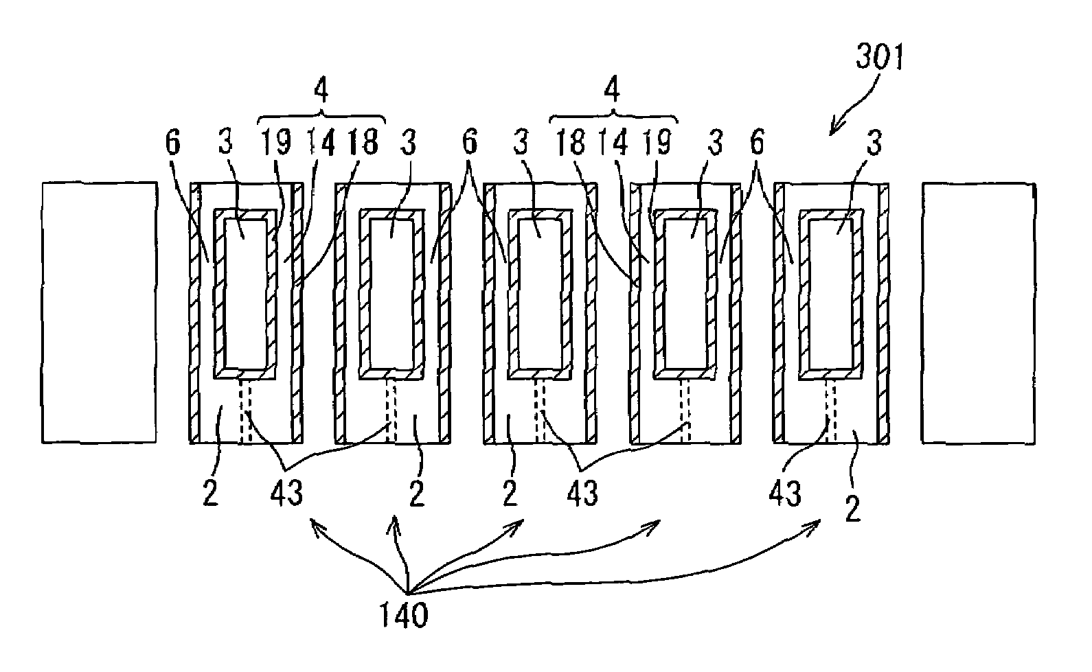
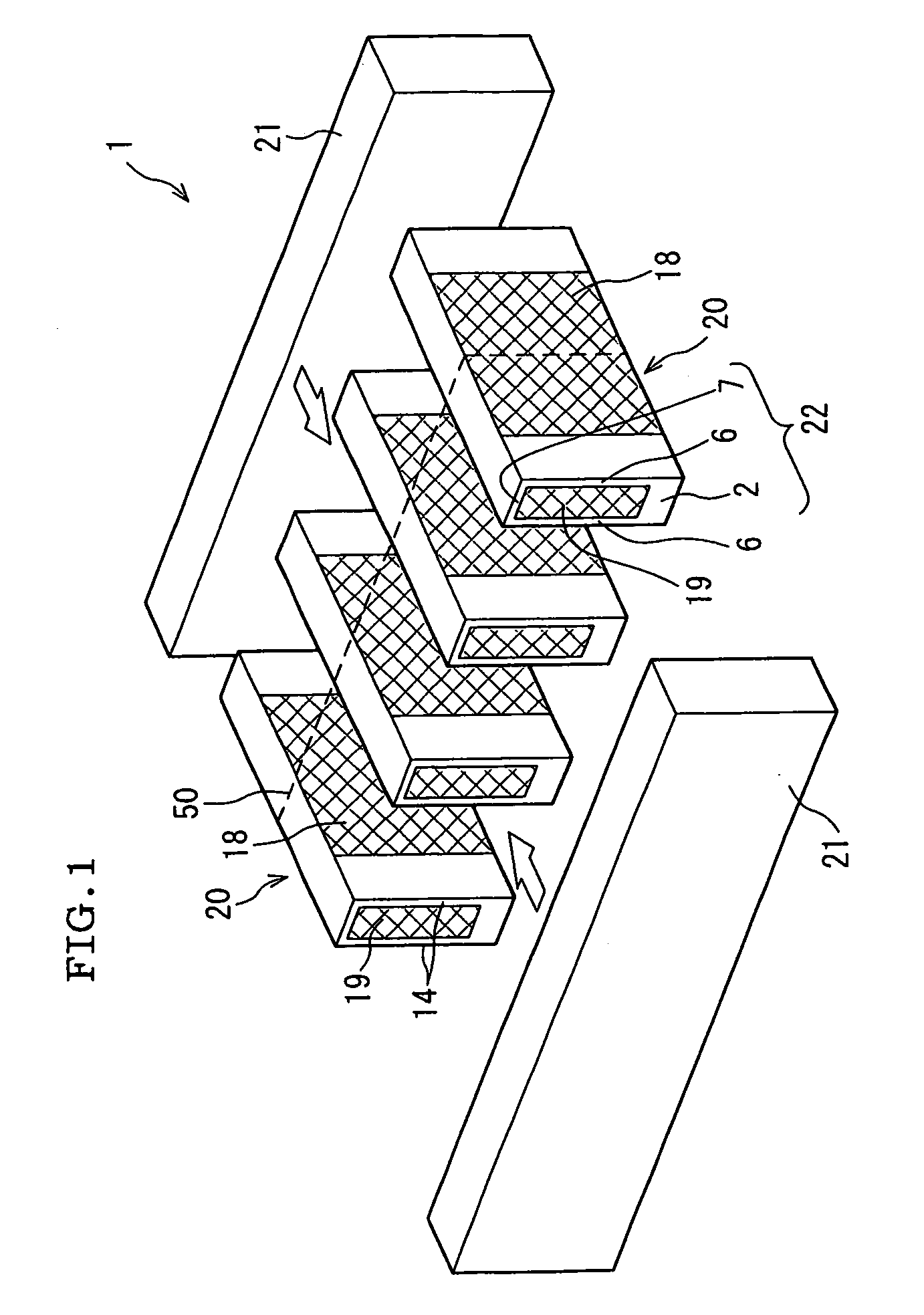
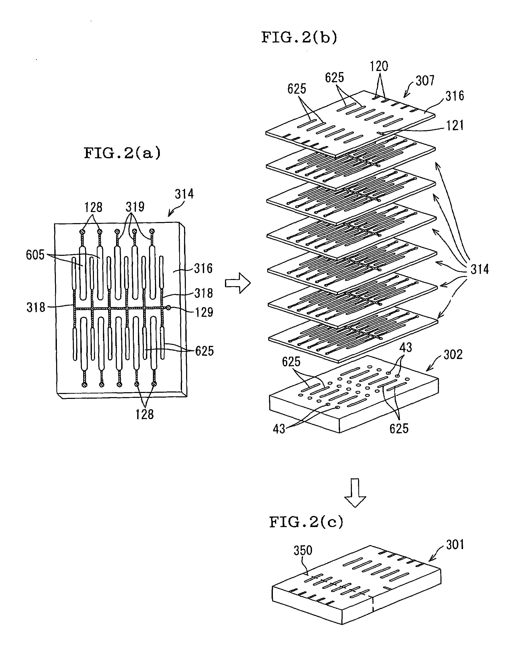
[0062]Embodiments of a cell driving type piezoelectric actuator of the present invention, and a method for manufacturing a cell driving type piezoelectric actuator according to the present invention will be described hereinafter appropriately with reference to the drawings, but the present invention is not interpreted, with limiting to these embodiments. Various changes, modifications, improvement, or replacements may be made based on knowledge of a person skilled in the art without departing from the sprit of the present invention. For example, the accompanying drawings show preferable embodiments of the present invention, therefore, the present invention is not limited to embodiments or information shown in the drawings. In implementing or verifying the present invention, means similar or equivalent to the means described in the present specification is applicable. Indeed, the means described hereinafter shows a preferable means.

[0063]FIGS. 1 and 8 are diagrams showing one embodim...


PUM


Abstract

A cell driving type piezoelectric actuator comprising: a plurality of cell driving bodies each comprising a wall portion, a cell formed by the wall portion, a piezoelectric body formed on at least one of wall portions and at least one pair of electrodes formed on the piezoelectric body; said piezoelectric operation portion being capable of changing a volume of the cell on which said piezoelectric operation portion is formed by its displacement, wherein the piezoelectric actuator comprises at least one pair of support bodies, the plurality of cell driving bodies are formed completely independent of one another and are connected to one another through at least one pair of support bodies, and the cell driving bodies and the support bodies are integrally formed by firing a green body of said piezoelectric actuator. A method for manufacturing the same is also disclosed.

Description

[0001]This application claims the benefit of Japanese Application 2003-155009, filed May 30, 2003, Japanese Application 2003-370594, filed Oct. 30, 2003, and Japanese Application 2004-154940, filed May 25, 2004, the entireties of which are incorporated herein by reference.BACKGROUND OF THE INVENTION[0002]1. Field of the Invention[0003]The present invention relates to a cell driving type piezoelectric actuator comprising a plurality of cells each being defined by wall portions, and capable of achieving a predetermined function due to the volume change of the cell(s) by displacement caused by a piezoelectric operative portion provided on the wall portions.[0004]2. Description of the Related Art[0005]It has passed a long time since an ink jet head was employed for a printer, facsimile machine, copying machine, and other printing apparatuses. In recent years, a non-impact system has been used especially in most of small-sized printers, and a clear image has been reproduced on paper by t...

Claims


Application Information

Patent Timeline
Patent Type & Authority Patents(United States)
IPC IPC(8): B41J2/045B41J2/055B41J2/135B41J2/14B41J2/145B41J2/16F04B17/00F04B43/04H01L27/20H01L41/083H01L41/09H01L41/187H01L41/22H01L41/27H02N2/00
CPCB41J2/14209B41J2/1609B41J2/164B41J2/1642F04B17/003F04B43/046H01L27/20H01L41/0831H01L41/273H10N39/00H10N30/501H10N30/053
Inventor TAKEUCHI, YUKIHISAKIMURA, KOJIIWATA, KOICHIYAMAMOTO, KAZUHIRO
Owner NGK INSULATORS LTD
Why Eureka
Try Eureka