Method for cutting a tubular structure at a drill floor and a cutting tool for carrying out such method

a tubular structure and drill floor technology, applied in the field of tubular structure cutting methods, can solve the problems of taking too much time, and achieve the effects of convenient cutting, efficient, fast and robust cutting of the tubular structure, and speeding up the cutting speed

Pending Publication Date: 2020-09-17
SMART INSTALLATIONS
View PDF23 Cites 1 Cited by
  • Summary
  • Abstract
  • Description
  • Claims
  • Application Information

AI Technical Summary

Benefits of technology

[0021]In an embodiment of the method in accordance with the invention, in the step of providing the cutting tool, a tool is provided, wherein the reaction member is provided with a further cutting element directed towards the non-rotatable cutting element for facilitating the cutting. Providing a cutting tool with a further cutting element on the reaction member further speeds up the cutting speed.
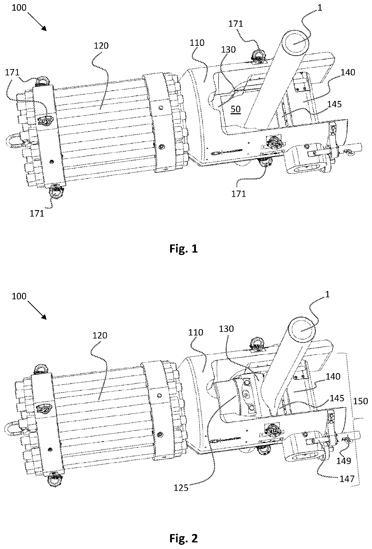
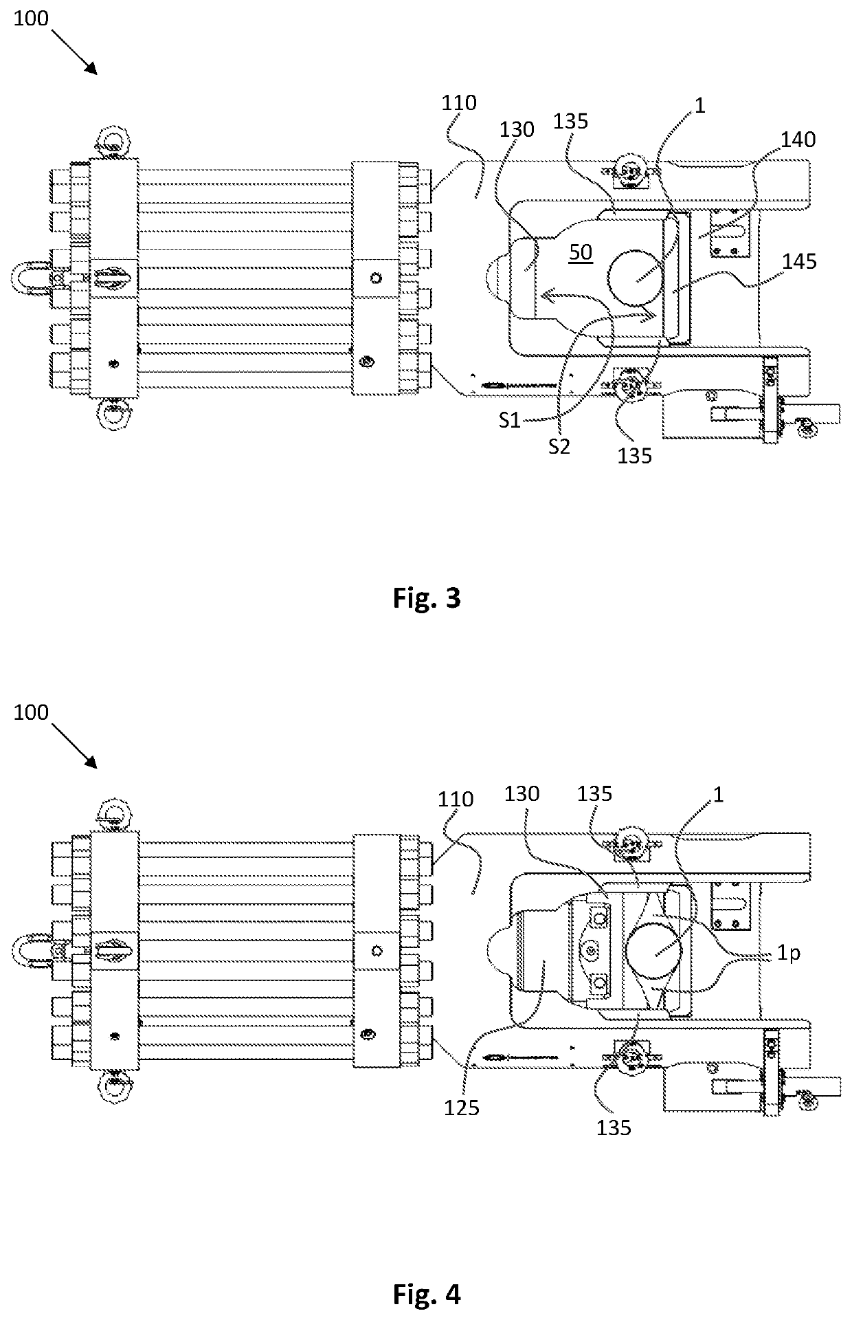
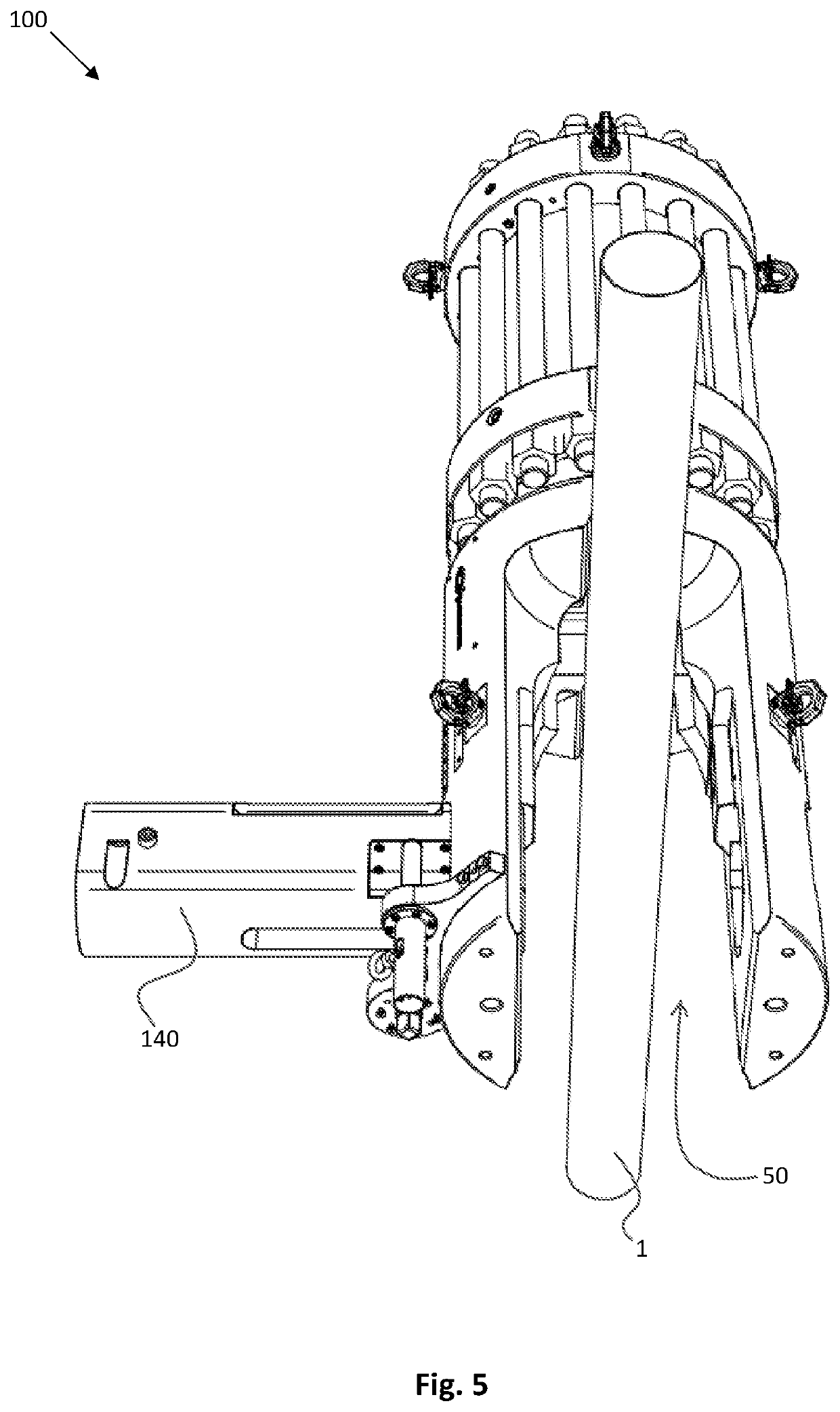
[0022]In a second aspect the invention relates to a cutting tool for use in the method in accordance with the invention, the cutting tool comprising: i) a tool body configured for receiving the tubular structure in an enclosure thereof; ii) an actuator mounted on the tool body at one side of the enclosure; iii) a non-rotatable cutting element provided on the actuator, the actuator with the cutting element being configured for carrying out a translational cutting movement through the enclosure including the tubular structure, and iv) a reaction member mounted at an opposite side of the enclosure of the tool body opposite to the cutting element for applying a reaction force on the tubular structure during cutting, wherein the actuator comprises a hydraulic main cylinder comprising a piston that is coupled to the non-rotatable cutting element via a piston rod, and wherein the actuator comprises an accumulator that is placed in fluid communication with the hydraulic main cylinder for storing and releasing energy, as needed, during the translational cutting movement of the non-rotatable cutting element. The cutting tool of this embodiment of the invention provides for a very efficient, fast and robust cutting of the tubular structure as the energy is applied in much smoother way than without the accumulator.
[0023]In an embodiment of the cutting tool in accordance with the invention the accumulator is placed inside the piston rod and communicates with the hydraulic main cylinder via a channel. When the actuator is designed very large, in order to be able to cut thick tubular structures, there is a lot of space available within the volume of the piston rod. This volume can be advantageously exploited for housing the accumulator without compromising the strength of the piston rod.
[0024]In a first variant the accumulator is used to control the force during cutting. If the forces are not properly controlled, there may be a risk that the system collapses. In order to achieve such controlled cutting, the accumulator is to be coupled to the low-pressure side of the piston in the hydraulic main cylinder, such that the actuator works against the accumulator pressure during cutting, i.e. the accumulator dampens the cutting movement and avoids high forces to be released when the object gives in during cutting.
[0025]In a second variant the accumulator is used to increase the force during cutting. In order to achieve such increased cutting force, the accumulator is to be coupled to the high-pressure side of the piston in the hydraulic main cylinder, such that the pressure in the accumulator adds to the hydraulic pressure applied to the high-pressure side of the piston. This variant will generate more force and also lets the cutting tool activate faster.
[0026]In an embodiment the reaction member forms part of a further actuator, which further actuator is configured for opening and closing said enclosure for receiving said tubular structure. This embodiment of the cutting tool is a bit more sophisticated. The reaction member that forms part of a further actuator facilitates that the cutting can be carried out quicker, thus saving cutting time.

Problems solved by technology

The problem with above cutting techniques is that it takes too much time.

Method used


Image

  • Method for cutting a tubular structure at a drill floor and a cutting tool for carrying out such method
  • Method for cutting a tubular structure at a drill floor and a cutting tool for carrying out such method
  • Method for cutting a tubular structure at a drill floor and a cutting tool for carrying out such method

Examples


Embodiment Construction

[0037]Various illustrative embodiments of the present subject matter are described below. In the interest of clarity, not all features of an actual implementation are described in this specifies cation. It will of course be appreciated that in the development of any such actual embodiment, numerous implementation-specific decisions must be made to achieve the devel-opers' specific goals, such as compliance with system-related and business-related constraints, which will vary from one implementation to another. Moreover, it will be appreciated that such a development effort might be complex and time-consuming, but would nevertheless be a routine undertaking for those of ordinary skill in the art having the benefit of this disclosure.

[0038]The present subject matter will now be described with reference to the attached figures. Various systems, structures and devices are schematically depicted in the drawings for purposes of explanation only and so as to not obscure the present disclos...


PUM

PropertyMeasurementUnit
reaction forceaaaaaaaaaa
pressureaaaaaaaaaa
cutting timeaaaaaaaaaa

Abstract

A method is for cutting a tubular structure, such as a drill string, at a drill floor of a drilling rig. The method includes the following steps: i) providing a cutting tool at the drill floor comprising a non-rotatable cutting element configured for carrying out a translational cutting movement through the tubular structure; ii) positioning the cutting tool in cutting position exterior to the tubular structure; iii) fixing the position of the cutting tool with respect to the tubular structure, and iv) activating the cutting tool for cutting the tubular structure by using a translation movement of the at least one cutting element through the tubular structure. A cutting tool is for use in such method.

Description

FIELD OF THE INVENTION[0001]The invention relates to a method for cutting a tubular structure, such as a drill string, at a drill floor of a drilling rig. The invention further relates to a cutting tool for use in such method.BACKGROUND OF THE INVENTION[0002]In drilling operations, such as operations on an oilrig, there is sometimes a need to cut tubular structures, such as casings, drill strings, production tubings and risers. Different techniques for cutting tubular structures have been developed. One of the most common ways to cut tubular structures at the drill floor is abrasive cutting from within the tubular structure, diamond wire cutting or a mechanical saw cutting. Typically, the tubular structure is cut in small sections, which are then taken away from the drill floor. Typical cutting time for a 30-inch casing is in the order of a few hours. The problem with above cutting techniques is that it takes too much time. Thus, there is a need for faster cutting techniques.SUMMARY...

Claims


Application Information

Patent Timeline
Patent Type & Authority Applications(United States)
IPC IPC(8): B23D21/00B23D15/04B23D29/00E21B29/00B26D1/08
CPCB23D29/002B23D15/04E21B29/00B26D1/08B23D21/006B23D21/00
Inventor BIRKELAND, PETTER
Owner SMART INSTALLATIONS
Why Eureka
Try Eureka