

Projection display unit
a technology of projection display and display unit, which is applied in the direction of picture reproducers, picture reproducers using projection devices, instruments, etc., can solve the problems of large variation in accuracy, difficulty in adjustment work, and reduction in yield and cos
- Summary
- Abstract
- Description
- Claims
- Application Information
AI Technical Summary
Benefits of technology
Problems solved by technology
Method used
Image

Examples
embodiment
[Configuration]
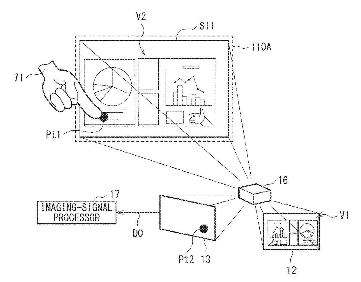
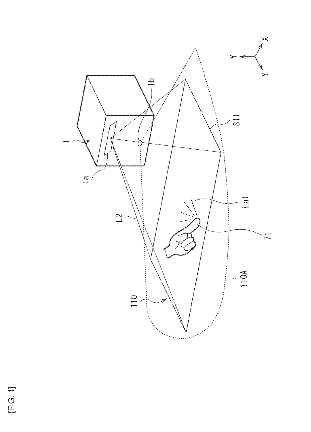
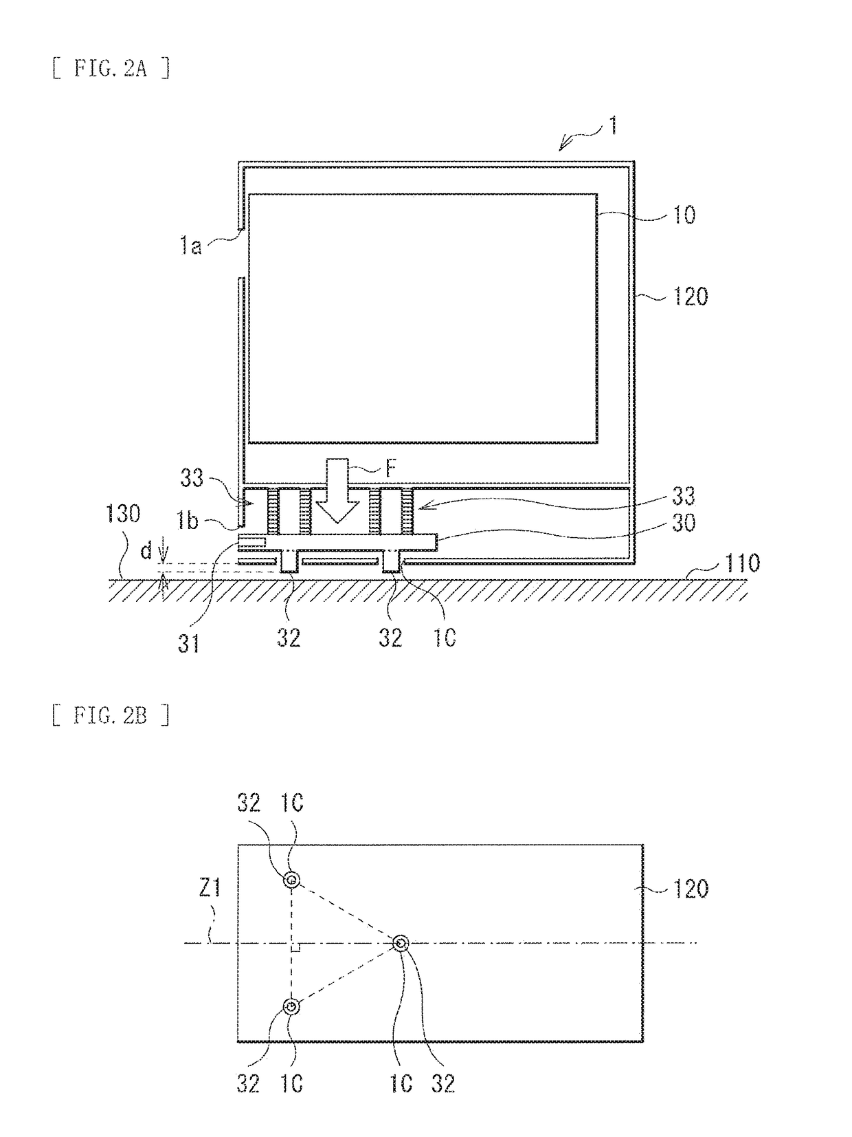
[0040]FIG. 1 illustrates an appearance and a use state of a projection display unit (a projection display unit 1) according to an embodiment of the disclosure. FIG. 2A illustrates an internal configuration of the projection display unit 1. FIG. 2A and FIG. 2B each illustrate a configuration of an undersurface of the projection display unit 1. FIG. 3 illustrates a functional configuration of the projection display unit 1.
[0041]The projection display unit 1 is, for example, a projector of a type that projects an image onto a region in proximity to the projection display unit 1, in a state of being installed on a top surface of a table, desk, stand, or the like, or on a wall (a projector of a so-called ultra-short focus type). A projection plane (a plane onto which an image is projected and displayed) 110 of the projection display unit 1 is, for example, on an extension surface of an installation surface (a surface on which the projection display unit 1 is placed) 130. T...
modification examples 1-1 to 1-3
[0082]FIG. 13A is a schematic diagram illustrating a configuration of a protrusion of the detection light-source section 30 according to a modification example 1-1. FIG. 13B is a schematic diagram illustrating a configuration of a protrusion of the detection light-source section 30 according to a modification example 1-2. FIG. 13C is a schematic diagram illustrating a configuration of a protrusion of the detection light-source section 30 according to a modification example 1-3. The configuration of the protrusion of the detection light-source section 30 is not limited to the above-described configuration of the protrusion 32. For example, as with the modification example 1-1 illustrated in FIG. 13A, the protrusion 32 may have a relatively large diameter (or width). Further, as with the modification example 1-2 illustrated in FIG. 13B, a plate-shaped member 32B2 may be further coupled to a protrusion 32B1. Furthermore, as with the modification example 1-3 illustrated in FIG. 13C, a t...
modification example 2
[0083]FIG. 14 is a schematic diagram illustrating a configuration of a projection display unit according to a modification example 2. In the present modification example, the housing 120 is configured to block the output optical path of the detection light-source section 30 in a predetermined tilting state. Specifically, the housing 120 has an opening 1b 1 on the output optical path of the detection light-source section 30 in the installed state, as with the above-described embodiment. However, the opening 1b1 is located not to include the output optical path of the detection light-source section 30 in a predetermined tilting state. For example, a factor such as a position and a size of the opening 1b1 is set such that, in a case where an angle (an angle α) formed with the installation surface 130 is equal to or less than a predetermined angle serving as a threshold, the output optical path of the detection light-source section 30 passes through the opening 1b1, but is blocked by th...
PUM
 Abstract
Description
Claims
Application Information