Integrated foam type headrest having different hardness, and manufacturing method thereof

Active Publication Date: 2017-11-23
DAYOU HLDG CO LTD +1
View PDF8 Cites 6 Cited by
  • Summary
  • Abstract
  • Description
  • Claims
  • Application Information

AI Technical Summary

Benefits of technology

[0015]According to the present invention having the above-described configuration, when a headrest is manufactured, a cushion member having a certain softness is provided at a cushion part of the headrest where the user's head is rested, and a main body of the headrest is formed by foaming a conventional foam material. Thus, the cushion part and the main body can be manufactured in the integrated foam type without the finishing process, thus providing a headrest having parts with different hardnesses. Thus, the headrest can be manufactured easily, the manufacturing cos

Problems solved by technology

However, there is a problem in that the stability and comfort of the user are reduced because the portion where the user's head is rested has the same hardness as that of the other portions.
However, there is a problem in that that it takes a much time and expense for processes after the foaming, such as finishing of the foamed the main body of the headrest, cutting of the main body, insertion of the cushion member, attaching of a tape to the cushion member, etc.. In addition, since the tape must be attached to the cushion member, as shown in FIG. 3, a loosening phenomenon occurs between a headrest cover and the cushion member as illustrated in part A. Further, creasing may occur in the headrest cover, which may easily cause defective packaging, and there is a high possibility that the portion where the user's head is rested may protrude.
Moreover, the assembly-type method does not provide a satisfactory effect for the passenger even when the cushion member having a thickness of equal to or greater than 15 mm is used.
However, the conventional integrated foam type headrest is problematic in that it is very difficu

Method used


Image

  • Integrated foam type headrest having different hardness, and manufacturing method thereof
  • Integrated foam type headrest having different hardness, and manufacturing method thereof
  • Integrated foam type headrest having different hardness, and manufacturing method thereof

Examples


Embodiment Construction

[0038]Hereinafter, a method for manufacturing an integrated foam type headrest having different hardness parts according to the present invention and a headrest manufactured by the method will be described in detail with reference to the accompanying drawings.

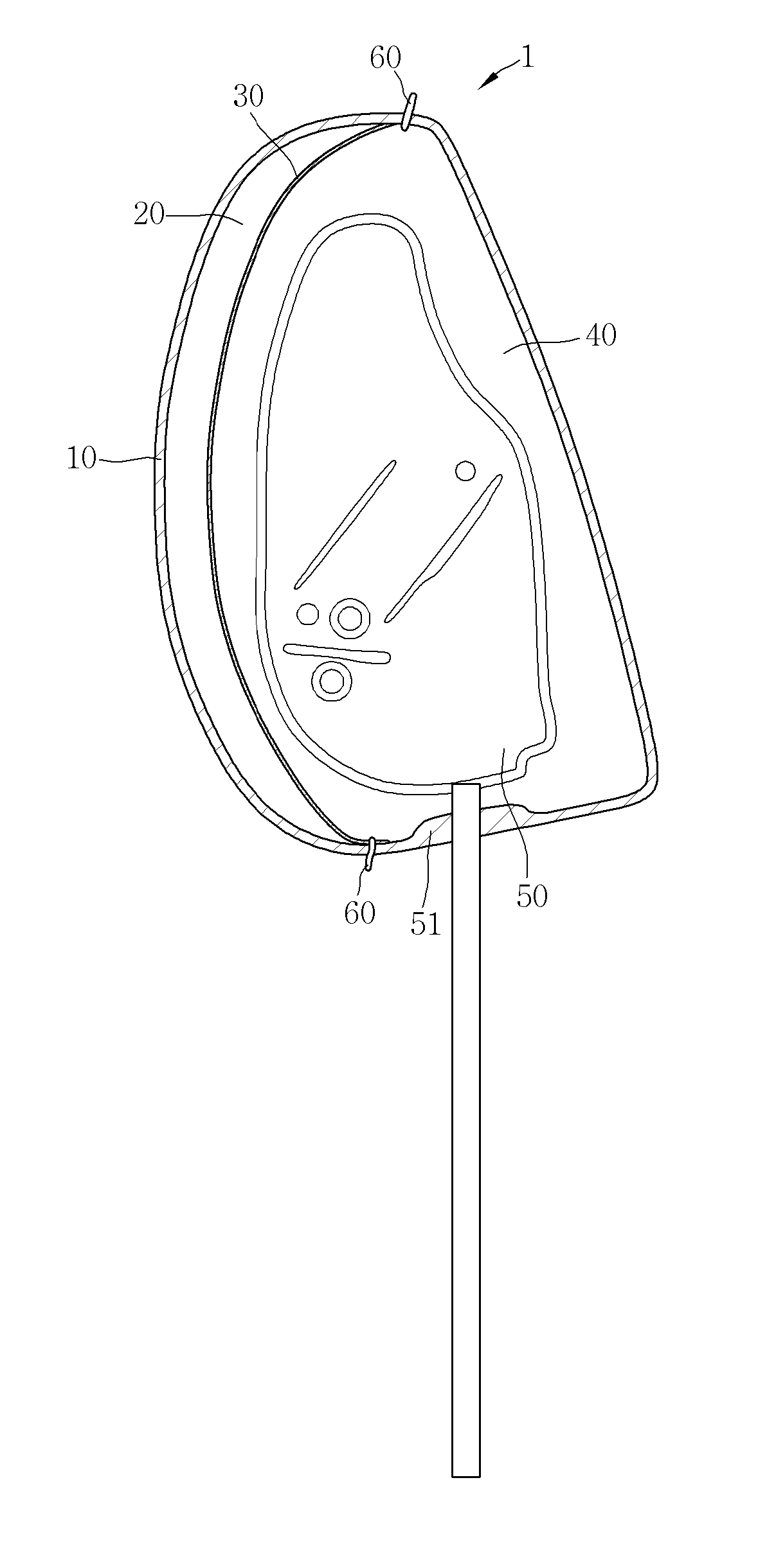
[0039]As shown in FIGS. 6 to 14, the integrated foam type headrest 1 having different hardness parts according to the present invention includes a headrest cover 10, a cushion member 20, a stay frame 50, and a foam material 40.

[0040]The headrest cover 10 uses fabrics typically used as the skin of the headrest, but may use any material that is applied to the headrest cover such as leather or the like without being limited thereto. The headrest cover 10 is provided at a lower end portion thereof with an opening into which the stay frame is inserted, which will be described later.

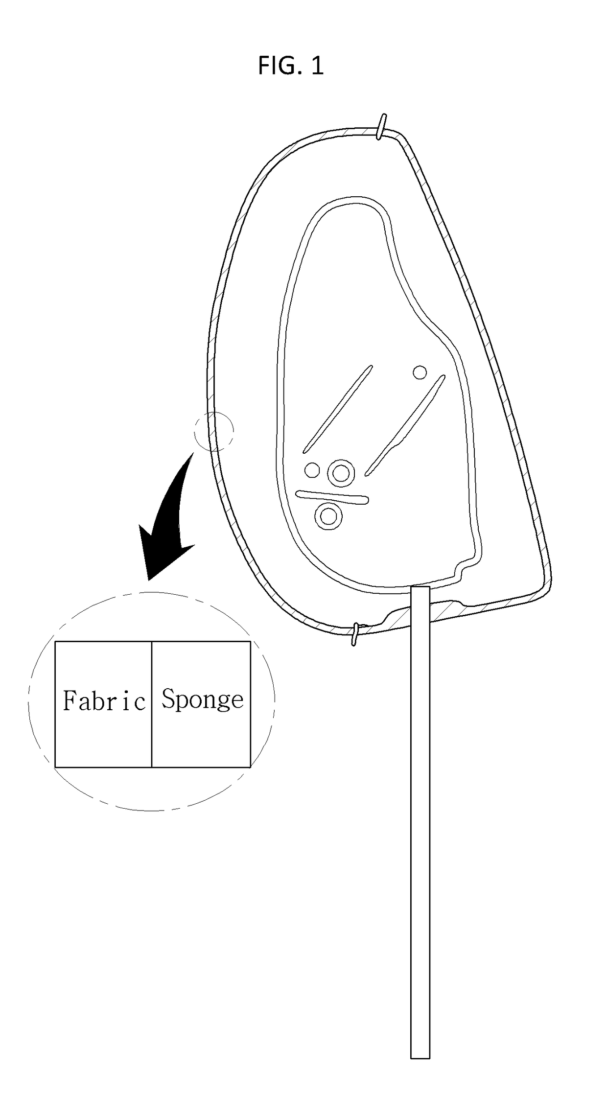
[0041]The cushion member 20 is attached to an inner surface of a portion of the headrest cover 10 where the user's head is rested. The cushion member 20 ...


PUM


Abstract

The present invention relates to an integrated foam type headrest and a manufacturing method thereof. The headrest includes: a headrest cover; a cushion member which is attached to the inside of the cover before forming foam of a foam material, and is made of material having high elongation and low resistant resilience; a partition member, attached to the inside of the cushion member, for preventing the foam material from penetrating the cushion member; a stay frame for fixing the headrest to a sheet; and a foam material which surrounds the stay frame and is filled in the inside of the cover of the headrest by means of foam-forming. Accordingly, even though a cushion member having a thickness of 10 mm or more is installed to satisfy the softness properties of the headrest, the cushion member can be stably adhered to the cover, and can be reliably installed even at a curved part. Furthermore, sewing convenience is achieved, and thus mass production is possible.

Description

TECHNICAL FIELD[0001]The present invention relates generally to an integrated foam type headrest. More particularly, the present invention relates to an integrated foam type headrest having different hardness parts, and a manufacturing method thereof, wherein a cushion part and a main body of the headrest can be manufactured in an integrated foam type, thus providing a headrest having parts with different hardnesses.BACKGROUND ART[0002]In general, a headrest is designed to be installed on the driver's seat and the passenger's seat of the vehicle to support the head of the driver or passenger so that the head can be rested while preventing the head from being tilted back and forth in sudden unintended accelerations or accidents.[0003]In a conventional headrest, the headrest is manufactured by inserting or injecting a flexible polyurethane, which is a foam material excellent in cushioning property, into a skin material sewn using a fabric having air permeability. As shown in FIG. 1, s...

Claims


Application Information

Patent Timeline
IPC IPC(8): B68G7/06B68G7/10B60N2/48
CPCB68G7/06B60N2002/4888B60N2/48B68G7/10B60N2/80B60N2/7017B60N2002/899
Inventor CHEON, WOOJUNG
Owner DAYOU HLDG CO LTD
Why Eureka
Try Eureka